CTP-1000D transformer comprehensive tester is a new generation of new type CT and Pt testing instrument, which is based on the traditional transformer volt ampere characteristic ratio polarity comprehensive tester based on voltage regulator, voltage booster and current transformer, after widely listening to users' opinions, after a lot of market research and in-depth theoretical research. The device adopts high-performance DSP and FPGA, and advanced manufacturing technology to ensure stable and reliable product performance, complete function, high degree of automation, high test efficiency and is in the leading level in China. It is a professional test instrument for transformer in power industry.
The basic wiring steps of CTP for CT test (see figure C.1) are as follows:
(1) Connect the grounding terminal on the left side of tester to protective ground with 4mm
2 wire.
(2) Connect one terminal of CT primary side and one terminal of secondary side to protective ground.
(3) Ensure that all other terminals of CT are disconnected from the transmission line and all other windings are open.
(4) Connect the secondary side of CT to S1 and S2 jack of tester "output" with 2.5mm
2 red wire and black wire, and connect the secondary side of CT to S1 and S2 jack of tester "sec" with 1.2mm
2 yellow wire and black wire. Note that the two black wires are connected to the same terminal of CT secondary side with protective grounding.
(5) Connect the primary side of CT to P1 and P2 terminals of "prim" of tester with green and black wires of 1.2mm
2. P2 is connected with the terminal of CT primary side connected to protective ground through black wire.
(6) Check the wiring and start the test.
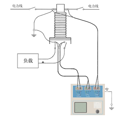
Figure C 1 Typical wiring mode
-
The wiring mode of the tester for CT test on the triangle connection transformer is shown in Figure C.2.
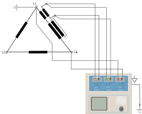
Figure C.2 Wiring mode of tester when testing on triangle connection transformer
2. The wiring mode of the tester for CT test of transformer bushing is shown in Figure C.3.
Note: the primary terminal H1 cannot be grounded, otherwise the primary side is grounded, then the tester cannot obtain the correct results.
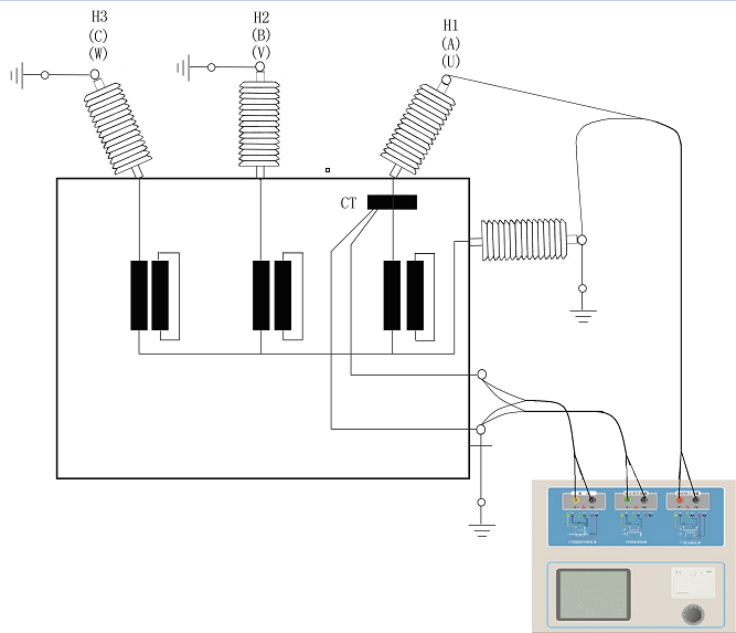
Figure C.3 wiring mode of testing instrument for CT of transformer bushing
3. The wiring mode of the tester when testing CT on GIS (SF6) switch is shown in figure C.4.
Attention: disconnect all switches connected with bus and close grounding switch.
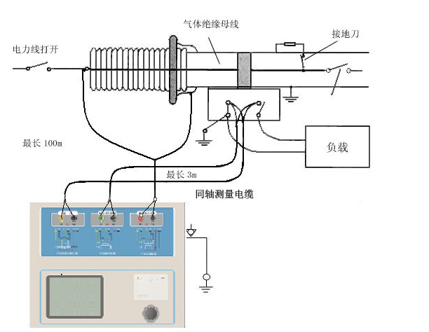
Figure C.4 Wiring mode of tester for CT test on GIS switch
Measuring principle of four terminal wiring
Applying a voltage source signal Vs to an impedance R will produce a current I, as shown in figure D.1.
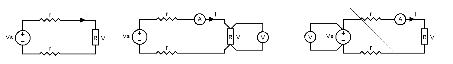
Figure D.1 Figure D.2 Figure D.3
To measure the impedance value, the voltage V on the impedance should be measured
Because there is a wire from the voltage source to the impedance to be measured, the wire has resistance R, which leads to V = Vs. therefore, if we want to accurately measure the impedance R, we can not simply replace V with the supply voltage Vs.
The measuring circuit of impedance R should adopt the wiring method in Fig. D.2. The voltmeter for measuring voltage must be connected from both ends of R separately with a wire to accurately measure the voltage value V of R. Because the two ends of R are connected by 4 wires, it is called 4-terminal connection. The wiring method in figure D.3 is wrong.
When CTP is used to measure the resistance, transformation ratio and excitation of transformer, 4-terminal wiring method is required, as shown in figure D.4.
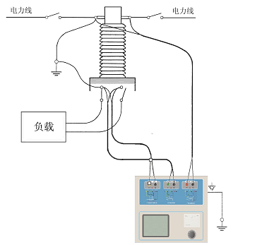
Figure D.4
The terminal connection method of the measured winding must be paid attention to in four terminal wiring. The connection in figure D.5 is correct, while that in figure D.6 and D.7 is wrong.
Figure D.5 Figure D.6 Figure D.7


