The detection signal generated by partial discharge is very weak, only at the level of microvolts. In terms of numerical value, it is easy to be submerged by external interference signals. Therefore, it is necessary to consider suppressing the influence of interference signals and take effective anti-interference measures.
The suppression methods for these interferences mentioned above are as follows:
1. Interference from the power supply can be suppressed using a filter in the power supply. This filter should be able to suppress all frequencies within the detector's bandwidth, but it should allow the low-frequency test voltage to pass.
2. Interference from the Earthing system can be eliminated by connecting the test circuit to the appropriate grounding point through separate connection. All nearby grounding metals should be well grounded and should not cause potential fluctuations.
3. External interference sources, such as static electricity or magnetic induction and electromagnetic radiation caused by high-voltage tests, nearby switch operations, radio emissions, etc., can be coupled into the discharge test circuit and mistakenly considered as discharge pulses. If these interference signal sources cannot be eliminated, it is necessary to process the test circuit to ensure good surface finish, large curvature radius, and shielding. A well-designed thin metal sheet, metal plate, or wire mesh is required for shielding. Sometimes the metal shell of the sample needs to be used as a shield. If conditions permit, a shielding laboratory can be built.
4. External discharge caused by test voltage. If the poorly grounded or suspended part of the test area is charged by the test voltage, discharge can occur, which can be distinguished from internal discharge through waveform judgment. Ultrasonic detectors can be used to locate this discharge. During the test, it should be ensured that all test objects and instruments are grounded reliably, and the equipment grounding point should not have rust or paint film. The grounding connection should be tightened with screws.

The suppression of interference is always considered from three aspects: interference source, interference pathway, and signal post-processing. Identifying the interference source and directly eliminating or cutting off the corresponding interference path is the most effective and fundamental method to solve interference. However, a detailed analysis of the interference source and interference path is required, and it is generally not allowed to change the original transformer operation mode. Therefore, the measures that can be taken in these two aspects are always very limited.
For various interferences that are coupled into the monitoring system through current sensors, various signal processing techniques are adopted to suppress them. Generally, partial discharge signals and interference signals are distinguished from the following aspects:; Power frequency phase, spectrum, pulse amplitude and amplitude distribution, signal polarity, repetition rate and physical position, etc.
There are two different approaches in anti-interference technology:
One is based on narrowband (frequency bands generally ranging from 10kHz to several 10kHz) signals. It picks up signals through narrow-band current sensors and band-pass filtering circuits with appropriate frequency bands, avoids various continuous periodic interferences, and improves the signal-to-noise ratio of the measured signals. This method is only suitable for a specific substation and is not convenient to use. In addition, due to the fact that the partial discharge signal is a broadband pulse, narrowband measurement can cause distortion of the signal waveform, which is not conducive to subsequent digital processing.
Another method is based on the processing of wideband (usually 10~1000kHz) signals. The detection signal contains most of the energy of partial discharge and a large amount of interference, but the signal-to-noise ratio is low.
The processing steps for these interferences are generally:
a. Suppress continuous periodic interference;
b. Suppress periodic pulse interference;
c. Suppress random pulse interference.
With the development of digital technology and the application of pattern recognition methods in partial discharge, this processing method often achieves good results. In post processing, many processing methods are consistent. It can be summarized as frequency domain processing and time domain processing methods. The frequency domain method utilizes the characteristic of periodic interference being discrete in the frequency domain to handle it; The time-domain processing method is based on the discrete characteristics of pulse type interference in the time domain. There are two implementation methods: hardware and software.
Due to the fact that the partial discharge pulse signal is a very weak signal, on-site electromagnetic interference will cause significant errors in the measurement results. Therefore, it is difficult to achieve accurate measurement. In order to improve measurement accuracy, in addition to the anti-interference measures introduced above, the following measures should also be taken during measurement:
1. The equipment used in the test should be halo free as much as possible, especially the test transformer and coupling capacitor Ck.
2. The performance of the filter should be good, achieving high-frequency isolation between the power supply and the measurement circuit.
3. The test time should be chosen as much as possible during periods with less interference, such as at night.
4. The parameter coordination of the measurement circuit should be appropriate, and the coupling capacitance should be as small as possible as the sample capacitance Cx, so that charges can be quickly converted between Cx and Ck during partial discharge.
5. The measuring equipment must be calibrated.

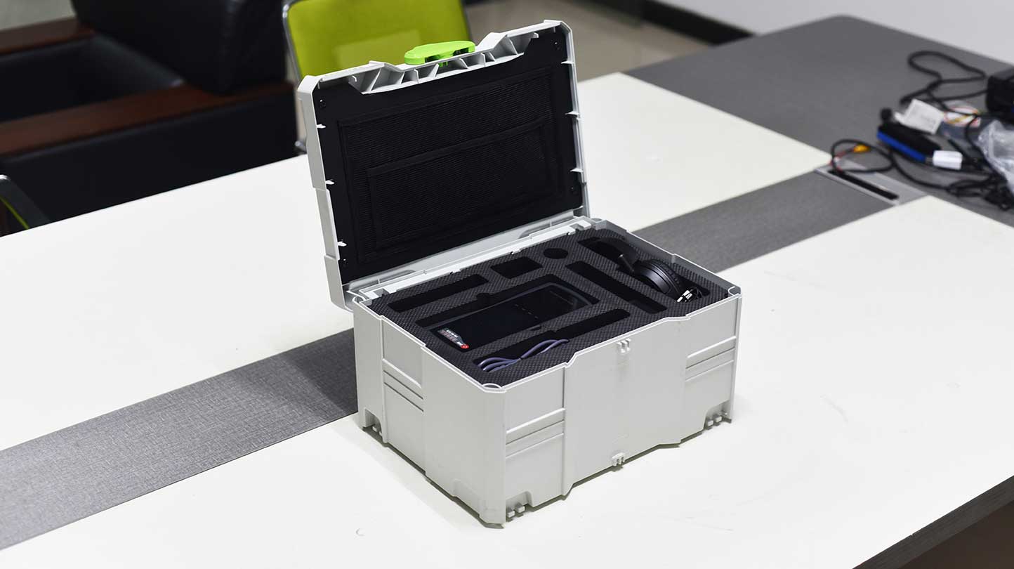
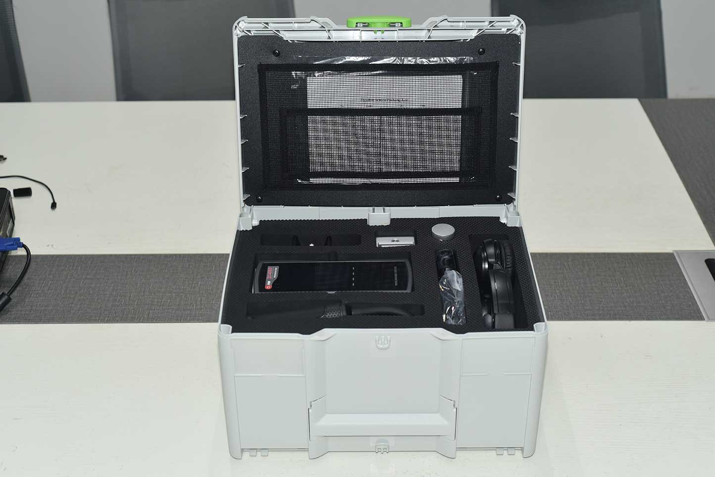
The ZC-830 partial discharge detector can be widely used for partial discharge detection in power systems, including insulation status detection of high-voltage switchgear, ring network cabinets, voltage/current transformers, transformers (including dry-type transformers), GIS, overhead lines, cables, and other equipment. The degree of discharge of electrical equipment is measured by the following indicators: 1. Partial discharge intensity detection: By measuring the discharge signal within one power frequency cycle, the intensity of partial discharge is characterized by the * value (dB) in the discharge pulse sequence. 2. Partial discharge frequency detection: The device measures the discharge signal within one power frequency cycle, extracts discharge pulses, and characterizes the frequency of partial discharge based on the number of discharge pulses.
Kvtester Electronics Technology Co.,Ltd. is a high-tech enterprise specializing in power testing, testing, research and development, production, and sales of testing equipment. It has been engaged in the electrical testing industry for many years, and its products are of high quality. We welcome customers to come and purchase.


