What are the troubleshooting methods for circuit resistance testers?
1. Fault phenomenon: the circuit resistance tester is connected to the 220V AC power supply, and the fan has no running sound. Press the "test switch", and the Ammeter and micro ohmmeter have no display.
Reason: 220V AC power supply blocked, fuse not installed or blown.
Troubleshooting: Check and troubleshoot. The fuse of the 100A instrument should not be less than 6A. If it blows again, please contact the manufacturer for resolution. (Do not connect to a DC or 380V AC power supply)
2. Fault phenomenon: press the "test switch" of the circuit resistance tester, the Ammeter displays no current, and the highest position of the micro ohmmeter displays "1".
Reason: The 100A current circuit is not properly connected. The tested switch is not closed.
Troubleshooting: Check the test line, reconnect, re clamp, and turn off the switch.
3. Fault phenomenon: The current tested by the circuit resistance tester is normal, and the highest micro ohm value displays "1".
Cause: The position of Voltage clamp is wrong. The measured circuit resistance value exceeds 2000. The voltage signal line is disconnected or not connected.
Troubleshooting: process the voltage signal circuit and clamp the Voltage clamp. Over range: Use a multimeter to measure the voltage values of P1 and P2, with resistance value=voltage value/current value.
4. Fault phenomenon: The output current of the circuit resistance tester is several tens of times smaller than 100A.
Reason: The power supply voltage is too low, the internal resistance of the power line is high or the contact is poor, and the voltage drop is too large when there is DC output, which cannot reach 190V. C1 and C2 terminals are loose. Poor contact between the tested circuit and the test clamp.
Troubleshooting: Use a qualified power supply and use a power cord that is too long or too thin to handle the tested circuit, and eliminate poor contact. When tightening terminals C1, C2, P1, and P2, appropriate force should be applied. (Test current 30a, reliable test value)
Attention: Circuit resistance testers are generally possible, and most of them can be found in the above reasons. Please refer to relevant methods to solve the problem.
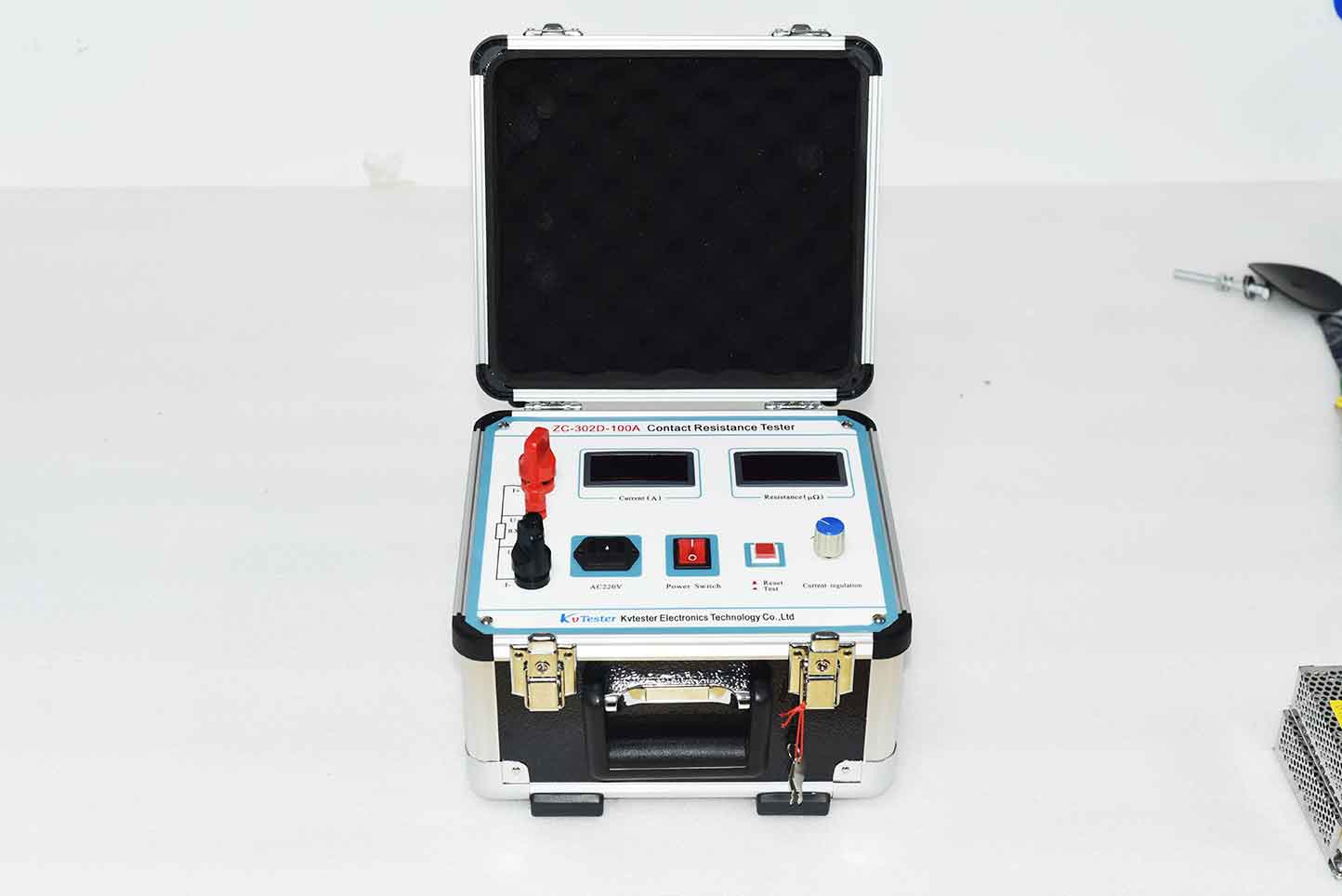
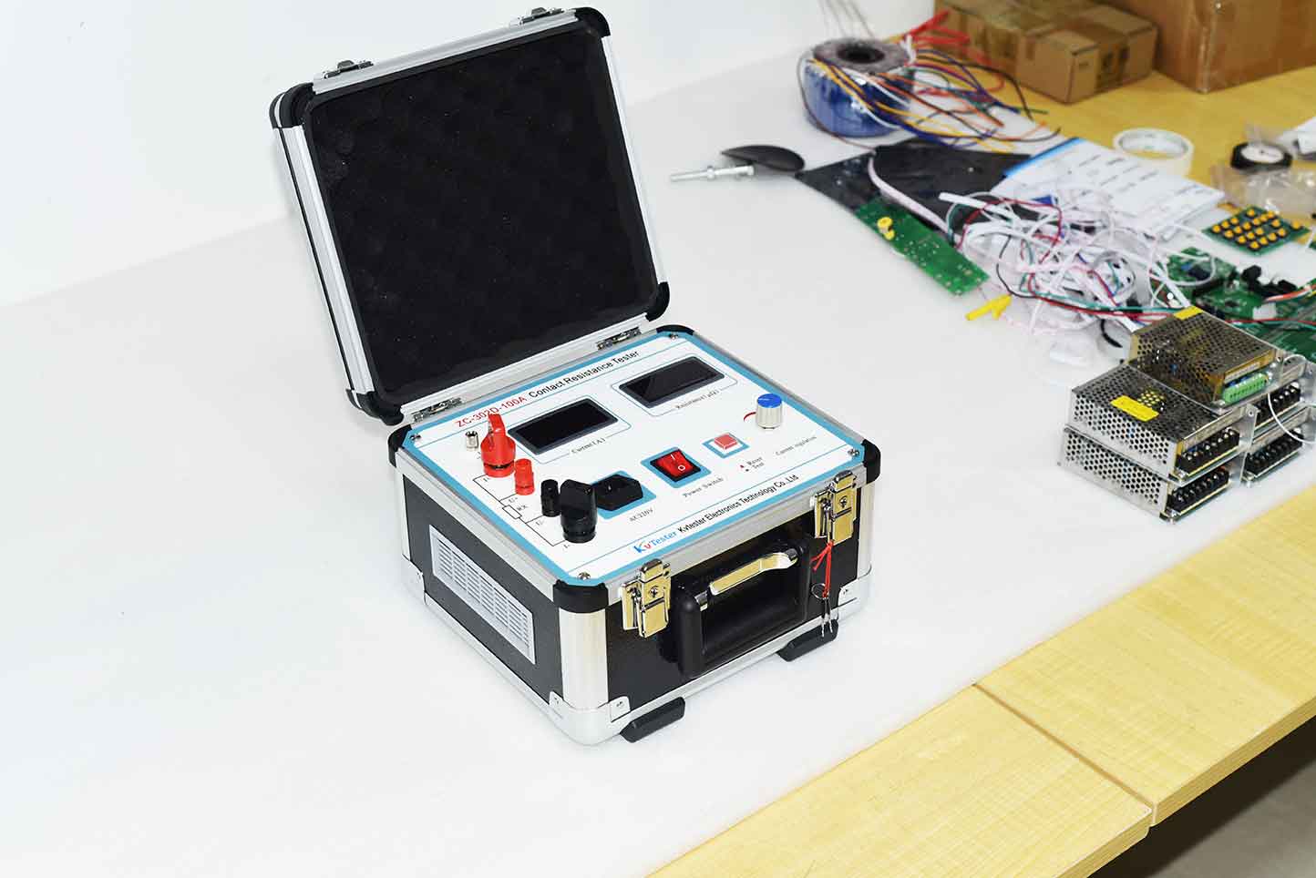
The ZC-302D-100A contact resistance test is based on a combination of high-frequency switching power supply technology and digital circuit technology. Suitable for measuring the circuit resistance of switch control equipment. The tester can measure the circuit resistance and display it on the monitor. Its accuracy and stability meet the requirements of most power systems for the maintenance of high-voltage switches and circuit resistance.
Product characteristics:
1. High current: using the latest battery technology, the tester can continuously output high current, overcoming the difficulty of Pulsed power instantaneous current. It can effectively breakdown the oxide layer between switches, thereby obtaining more accurate results.
2. Strong anti-interference ability: Even under strong interference conditions, the number of * test data displayed on the LCD screen is within ± 1 range.
3. Long service life: All precise resistors used in the tester can reduce the impact of temperature on measurement results, and military connectors can enhance vibration resistance.
4. Convenience: Smaller and lighter.
Kvtester Electronics Technology Co.,Ltd. is a high-tech enterprise specializing in power testing, testing, research and development, production, and sales of testing equipment. It has been engaged in the electrical testing industry for many years, and its products are of high quality. We welcome customers to come and purchase.


