1. Do you know how many reactors to bring for the withstand voltage test?
Step 1: Before going to the site, it is necessary to clarify the information of the tested object in advance. Find a person to inspect the electrical equipment nameplate at the construction site in advance, or communicate with the owner or engineering contractor to understand some important information, such as the voltage level, length, cross-sectional area of the cable, and the treatment of intermediate joints; Nameplate and manufacturer information of the transformer.
Step 2: Use a series resonance mini program to deduce the test plan based on known conditions, and determine how many reactors to use, how much power excitation transformer to use, how much power generator to use, and how much square power line to use.
2. Unable to find resonance point, failed frequency finding (high voltage displayed continuously within 0.00kV or 0.5kV during frequency finding, no voltage peak found), you can gradually eliminate it according to the following steps:
Step 1: Troubleshooting wiring issues Solution:
① Check if all wiring is correct, and measure the continuity of each test wire to see if it is broken or in poor contact; The high-voltage wire should be suspended and not dragged to the ground. Whether all grounding wires are connected (the power supply, high-voltage tail of the excitation transformer, voltage divider, grounding terminal or outer armor of the tested object's shell, and discharge rod should be reliably connected to the ground);
② Focus on whether the voltage divider wire is properly connected and whether the connection and disconnection are good;
③ Is there any looseness or poor contact in the equipment wiring terminal;
Step 2: Theoretical calculation: Based on the known inductance and capacitance of the current configuration, whether the frequency of capacitance calculation is within 30-300Hz. Calculate the series resonant frequency and current as follows:
8.7/15kV cable, 120mm ², 1.5kM; Reactor 27kV, 1A, 80H. Or substitute the cable parameters to obtain the electrical capacity. It has been calculated that the current of a single reactor is insufficient. Assuming two reactors are connected in parallel, the high-voltage rated current can reach 2A. The inductance of the two reactors connected in parallel is 80/2=40H, and the current can be calculated by clicking on the upper right corner of the frequency chamber at 40.276Hz. By substituting the test voltage of 17.4kV, frequency of 40.276Hz, and cable capacitance, the test high-voltage current can be calculated as shown in Figure 1.719A. We assume that two reactors are used in parallel, with a rated current of 2A and 1.719A less than 2A, which means this method is feasible.
Solution: According to the number of reactors, change the inductance through series or parallel connection, and change the test frequency to within 30-300Hz.
Step 3: Incorrect interface settings:
① Solution: Focus on the starting voltage setting (220V starting voltage 20V cannot be found to increase to 30V; 380V 30V cannot be found to increase by 40 or 50V, with a maximum of 50V);
② Solution: Change the frequency step from large to small (frequency step to 0.1Hz or 0.5Hz);
3. Boost voltage cannot rise or flash over protection is reported. Please check the equipment and wiring. How can the undervoltage fault be resolved?
Exclusion 1: Incorrect use of starting voltage and voltage tap settings:
Solution: Set the starting voltage to lower it from 30V to 20V or 15V; Calculate how to use a lower voltage output as much as possible when the voltage is met, such as changing from 6kV to 3kV output wiring method; Is the setting voltage of overvoltage protection set too low? For example, if the voltage rises to 100kV and the overvoltage is set to 105kV, it is incorrect. According to the 1.1 times withstand voltage target setting, 110kV should be set
① The reactor is placed on the car or on a platform with iron plates, forming a magnetic field eddy current and causing power loss;
② The bottom plate of the reactor is affected by moisture, soil, and flashover protection due to discharge after stacking up and down;
③ The power of the generator is reduced, and the supply voltage drops or becomes unstable when the load is boosted;
④ The gear selection of the excitation variable voltage contact is incorrect, for example, the 1.5KV tap can increase by up to 45KV
4. Display fault: "Constant speed overcurrent"
Solution: The fault "constant speed overcurrent" is caused by a short circuit in the output of the host variable frequency power supply. Please check the wiring from the host variable frequency power supply output to the low-voltage side of the excitation transformer for any issues.
5. Jump open when starting
Solution: The rated value of leakage protection is too small, and the variable frequency power supply has a different frequency and high starting current. It is necessary to bypass the leakage protection for wiring, or replace the leakage protection switch dedicated to large variable frequency power supplies
6. The excitation transformer does not know how to select the voltage output:
The principle of selecting voltage taps: First, meet the withstand voltage target and select voltage taps
The 1.5kV voltage output is suitable for circuit breakers, transformers, etc. of 10kV voltage level, 3kV and 5kV are suitable for transformers, circuit breakers, etc. of 35kV voltage level, 6kV or 12kV are suitable for withstand voltage tests of 110kV main transformers, GIS or higher level electrical equipment. Generally speaking, the high voltage that can be raised at each voltage outlet is calculated by 30 times, for example, the voltage that can be raised at 1.5kV outlet is 1.5 × 30=45kV (The premise is to match the appropriate number of reactors in series and parallel to achieve this)
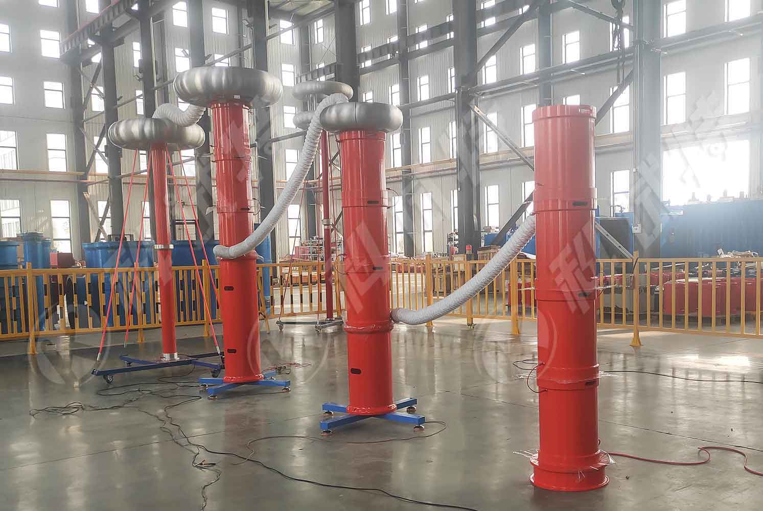
The ZCVF-A-1000kVA-400kV variable frequency series resonance testing system mainly targets 10kV, 35kV, 110kV, and 220kV cables; 220kV/240MVA main transformer fully insulated; Design and manufacture of AC withstand voltage tests for 110kV and 220kV GIS, switches, and circuit breakers. The reactor adopts multiple independent designs, which can meet the requirements of high-voltage and small current equipment testing conditions, as well as low-voltage AC withstand voltage testing requirements such as 10kV cables. It has a wide range of applications and is an ideal withstand voltage equipment for local, municipal, and county-level high-voltage testing departments and power installation and maintenance engineering units. The device mainly consists of a variable frequency control power supply, excitation transformer, reactor, and capacitor voltage divider.
Kvtester Electronics Technology Co.,Ltd. is a high-tech enterprise specializing in power testing, testing, research and development, production, and sales of testing equipment. It has been engaged in the electrical testing industry for many years, and its products are of high quality. We welcome customers to come and purchase.


