The working principle of the lightning impulse voltage generator test device is based on the Marx circuit principle of parallel charging and series discharging of multi-stage capacitors. By accurately controlling the capacitor charging and discharging process and waveform parameters, it generates lightning impulse voltage waveforms that meet the standards. Its core mechanism includes energy storage, discharge conversion, and waveform adjustment, as follows:
1. Core working principle
① Marx circuit energy storage
a. The device adopts a multi-stage capacitor parallel charging structure, which converts AC power into DC power through a rectification circuit and charges the capacitors at each stage to a preset voltage.
b. During the charging process, the protective resistor ensures uniform charging of all levels of capacitors and avoids local overvoltage.
② Discharge conversion mechanism
a. When an impulse voltage needs to be generated, the control system triggers the first stage ignition ball gap, causing the capacitors of each stage to be connected in series step by step through the intermediate ball gap.
b. After series connection, the total capacitance decreases to 1/n of the single-stage capacitance (n is the number of stages), and the total voltage is superimposed to n times the single-stage voltage, forming a high voltage pulse.
③ Waveform parameter adjustment
a. Adjust the output waveform parameters through the wave head resistance (Rf) and wave tail resistance (Rt):
b. Wave head resistance: controls the voltage rise time and determines the steepness of the waveform.
c. Tail resistance: controls the duration of voltage and determines the speed of waveform attenuation.
d. Typical waveforms such as 1.2/50 μ s (voltage wave) or 8/20 μ s (current wave) are achieved by adjusting the resistance value.
2. Typical application process
① Charging stage
a. After rectification, the high-voltage power supply charges the capacitors in parallel through charging resistors until the set voltage is reached.
b. Protect the resistor to isolate the charging and discharging circuits, ensuring safety.
② Discharge trigger
a. The control system sends ignition pulses, causing the first stage ignition ball gap to break through, triggering a chain discharge of intermediate ball gaps at all levels.
b. The capacitor transitions from a parallel state to a series state, and the voltage is added to the load capacitor (test end).
③ Waveform generation and measurement
a. The load capacitor and the capacitor discharge through the wave head/tail resistor, forming an impulse voltage waveform.
b. The voltage divider collects waveform data, and the oscilloscope records and analyzes waveform parameters to determine the withstand voltage performance of the test sample.
3. Key technical parameters
① Voltage output capability
a. The nominal voltage range is usually from tens of kV to MV level, and the higher the number of stages, the higher the output voltage.
b. The voltage utilization coefficient (the ratio of output voltage to charging voltage) is generally greater than 90%.
② Waveform accuracy
The waveform parameter error must meet the standard (such as GB/T 16927.1), for example:
Wavefront time (T1): 1.2 μ s ± 30%
Half peak time (T2): 50 μ s ± 20%
③ Synchronization and Control
a. The triggering synchronization accuracy is better than 1 μ s, ensuring the consistency of multi-level discharge.
b. The automation control system supports precise adjustment of voltage amplitude, polarity, and waveform parameters.
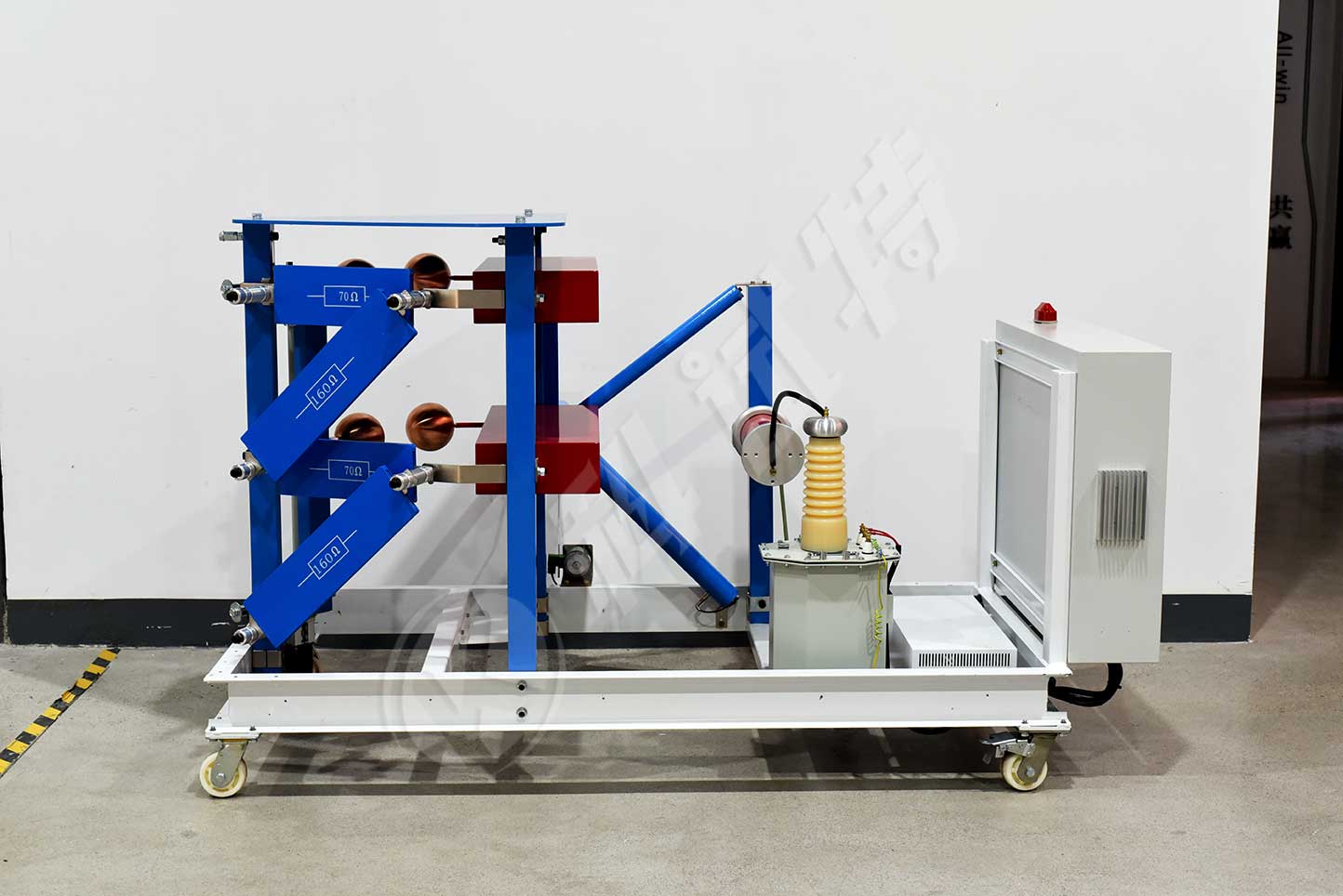
The ZCCJ-800kV/80kJ impulse voltage generator adopts a four column H structure, with a steel bracket consisting of a single flange and a parallel external single capacitor, forming a stable structure consisting of one stage. The main equipment is of 8 levels, forming a combined tower structure, with each level stacked step by step for easy disassembly and maintenance, and the overall structure is stable.
This set of equipment is mainly designed to meet the lightning full wave and steep wave waveform tests of electrical equipment such as power insulators.The basic configuration of the equipment includes a charging device, an impulse voltage generator body, a weak damping capacitor voltage divider, a steep wave device, a fast resistor voltage divider, and other control and measurement devices.
Kvtester Electronics Technology Co.,Ltd. is a high-tech enterprise specializing in power testing, testing, research and development, production, and sales of testing equipment. It has been engaged in the electrical testing industry for many years, and its products are of high quality. We welcome customers to come and purchase. Service hotline: 0086-27-81778799, to learn more, visit the official website: www.kvtester.com


