As a core tool for evaluating the insulation status of electrical equipment, partial discharge detectors play a crucial role in early fault warning and condition monitoring. However, their technical characteristics and application scenarios still have inherent shortcomings and limitations. The following is a systematic analysis from the dimensions of technical principles, environmental interference, detection blind spots, and economic costs:
1. Inherent defects caused by technical principles
① Signal coupling and attenuation issues
a. Coupling efficiency dependence:
Different detection methods (such as HFCT, UHF, AE) require specific coupling paths to obtain signals. For example:
The HFCT sensor needs to be clamped on the grounding wire. If there is a shunt or electromagnetic shielding on the grounding wire, the signal amplitude may attenuate to unrecognizable levels;
UHF sensors in GIS equipment are susceptible to the influence of metal cavity waveguide effect, resulting in complex signal propagation paths and positioning errors.
b. Nonlinear signal attenuation:
When high-frequency signals propagate in long cables or complex structures, the attenuation coefficient increases exponentially with frequency. For example, the attenuation of UHF signals in a 10 meter cable may exceed 40dB, causing remote discharge signals to be overwhelmed by noise.
② Confusion in identifying discharge types
a. PRPD pattern similarity:
The PRPD spectra of suspended discharge, corona discharge, and surface discharge may have overlapping regions (such as positive and negative half cycle symmetry, phase distribution width), which are difficult to distinguish 100% solely based on spectral features.
b. Composite discharge interference:
In actual equipment, there may be multiple types of discharges simultaneously (such as metal tip corona discharge and insulation internal hole discharge superimposed), leading to misjudgment of diagnostic results.
2. Difficulties in environmental interference and noise suppression
① The uncontrollability of electromagnetic interference (EMI)
a. Strong interference sources in substations:
The electromagnetic noise spectrum generated by switch operation, corona discharge, wireless communication base stations, etc. covers the frequency band of partial discharge signals (kHz~GHz), for example:
50Hz power frequency harmonics (150Hz, 250Hz, etc.) may be superimposed on the discharge pulse, causing distortion in PRPD phase analysis;
Transient overvoltage (nanosecond pulses) generated by lightning strikes or circuit breaker operations may trigger false alarms in the detector.
b. Anti interference technology bottleneck:
Although filters, wavelet denoising, and adaptive thresholding algorithms are used, there may still be residual noise bases under strong interference (such as noise amplitudes exceeding 30% of the discharge threshold), which can affect the signal-to-noise ratio (SNR).
② Mechanical vibration and acoustic interference
a. Limitations of Ultrasonic Testing:
Background noise: The frequency spectrum of mechanical noise such as fan, pump, and transformer iron core vibration (20kHz~200kHz) overlaps with the ultrasonic frequency band generated by partial discharge, leading to false triggering of AE sensors;
Propagation path attenuation: The attenuation coefficient of ultrasonic waves in metal shells can reach up to 1dB/cm (high frequency band), and the remote discharge signal may be completely attenuated.
3. Detecting blind spots and positioning errors
① Limitations on spatial positioning accuracy
a. Time difference positioning error:
In compact equipment such as switchgear, the sensor spacing may be less than 1 meter, and the time resolution needs to reach nanosecond level to meet centimeter level positioning accuracy. For example:
If the sensor sampling rate is only 100MS/s (with a time resolution of 10ns), the corresponding spatial error can reach 3 meters;
In practice, higher sampling rates (such as 1GS/s) and synchronous clock technology are required, but the cost significantly increases.
b. Multipath propagation interference:
In GIS or transformers, electromagnetic waves may propagate through multiple paths such as metal casings and insulators, leading to deviations in time difference calculations. For example, UHF signals may reflect at GIS corners, causing false positioning points.
② Insulation structure shielding effect
a. Deep defect invisibility:
For thick insulation layers (such as XLPE insulation layers with a thickness of 10mm or more in high-voltage cables), internal discharge signals may be completely absorbed during propagation. For example:
In a cable with a diameter of 50mm, the signal strength at the discharge point 3mm away from the surface is only 1/10 of the surface discharge;
If the discharge point is located near the cable core, it may be completely undetectable by external sensors.
4. Adaptability limitations of application scenarios
① Difficulty in detecting dynamic load devices
a. Motor and frequency converter interference:
In variable frequency drive motors or new energy inverters, the pulse noise generated by PWM switching frequency (kHz level) may cover partial discharge signals. For example:
In wind turbine gearbox motors, the electromagnetic interference (EMI) spectrum generated by IGBT switches overlaps with the discharge signal, resulting in a false alarm rate of up to 40%;
Synchronous sampling techniques (synchronized with PWM trigger signals) or band stop filters are required, but this will increase system complexity.
② Reliability issues in extreme environments
a. High temperature/high humidity/corrosive environment:
The material of the sensor housing (such as ABS plastic) may deform above 85 ℃, leading to seal failure;
Salt spray environment may corrode the surface of metal sensors, reduce contact impedance, and introduce noise;
A case study of an offshore wind farm shows that unprotected UHF sensors have a failure rate of 30% within one year.
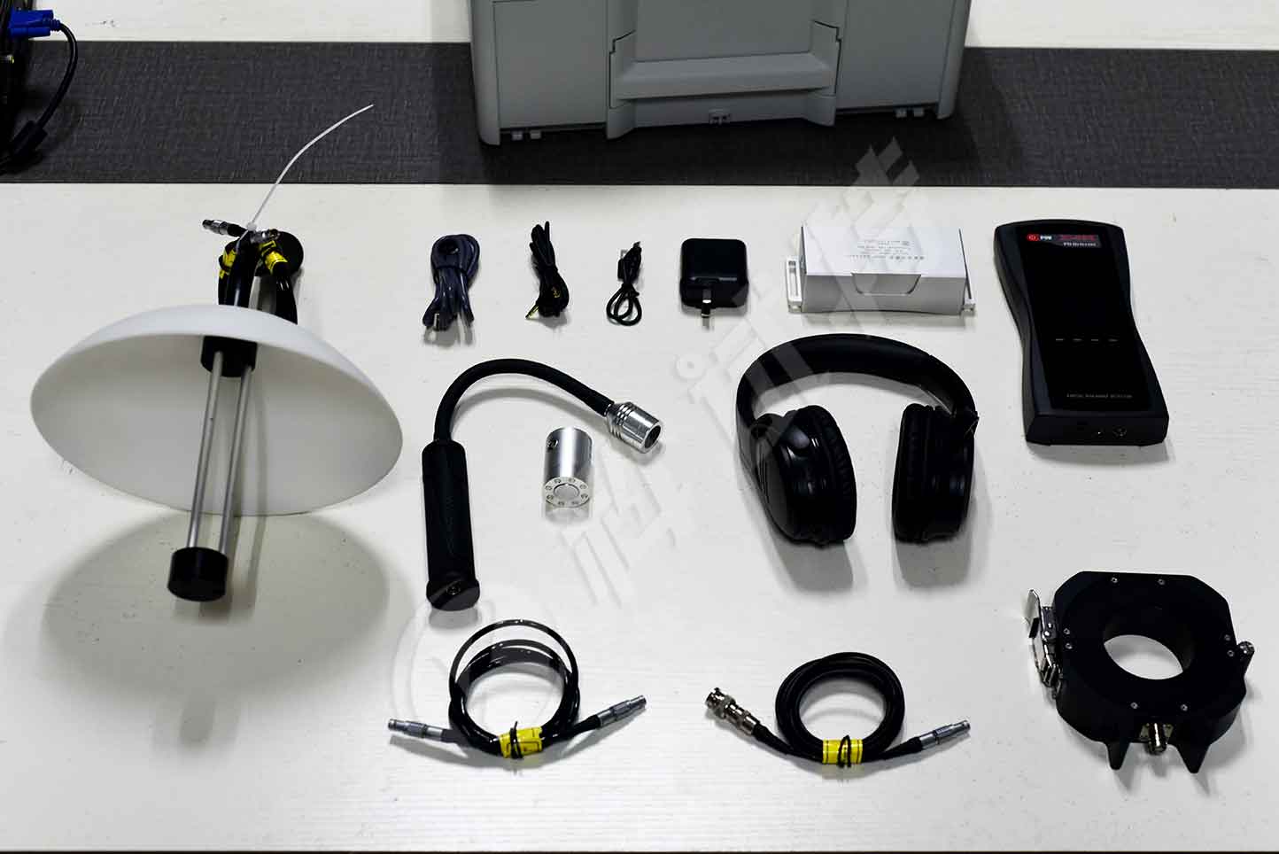
The ZC-830 partial discharge detector can be widely used for partial discharge detection in power systems, including high-voltage switchgear, ring main unit, voltage/current transformers, and transformers (including dry-type transformers) GIS、 Insulation state detection of overhead lines, cables and other equipment
Kvtester Electronics Technology Co.,Ltd. is a high-tech enterprise specializing in power testing, testing, research and development, production, and sales of testing equipment. It has been engaged in the electrical testing industry for many years, and its products are of high quality. We welcome customers to come and purchase. Service hotline: 0086-27-81778799, to learn more, visit the official website: www.kvtester.com


