The variable-frequency series resonance testing system achieves resonance between the inductance and the capacitance of the tested object by adjusting the power frequency, thereby generating high voltage on the tested object and achieving efficient and low-energy insulation performance testing. Its core principle is to utilize the physical characteristics of LC series resonance, combined with variable-frequency technology, to achieve precise control of the test voltage. The following is a detailed explanation of the working principle:
1. Basic physical principle: LC series resonance
① Resonance condition
When an inductor (L) is connected in series with a capacitor (C), the total impedance of the circuit is: Z=R+j(ωL− 1/ωC)
Where R represents the loop resistance, and ω=2πf denotes the angular frequency.
Resonance occurrence condition: ωL=1/ωC, i.e., f=1/2π LC
At this point, the circuit impedance is at its minimum (with only resistor R remaining), the current reaches its maximum value, and the voltages across the capacitor and inductor cancel each other out. However, the voltage across the test object (capacitor) can reach Q times the input voltage (Q is the quality factor).
② Quality factor (Q value)
Q= R/ωL=1/ωCR, representing the efficiency of energy exchange in a resonant circuit.
The higher the Q value, the greater the voltage amplification factor on the test object (usually ranging from tens to over a hundred).
The Q value is influenced by factors such as loop resistance, inductance loss, and capacitive dielectric loss.
2. System working process
Variable frequency power supply output
a. A variable-frequency power supply converts mains frequency (50Hz) AC power into sine waves with adjustable frequency (typically 20-300Hz).
b. By adjusting the output frequency, the inductance (L) and the capacitance (C) of the tested object can satisfy the resonance condition.
② Establishment of resonance state
a. When the test frequency f equals the resonant frequency f0=1/2π LC, resonance occurs in the circuit.
b. At this time, the variable-frequency power supply only needs to output a smaller voltage Uin, and the voltage Uc on the tested object is: Uc=Q⋅Uin
③. Voltage generation and control
a. By adjusting the frequency of the variable-frequency power supply, the resonance point can be precisely controlled, thereby stabilizing the output of high voltage.
b. The capacitive voltage divider monitors the voltage of the tested object in real time and feeds it back to the control system, achieving closed-loop regulation.
3. Key technology implementation
① Automatic tuning function
a. Frequency sweeping process: The system automatically scans within a set frequency range (such as 20-300Hz) to find the resonance point.
b. Fine adjustment stage: Fine adjustment is made near the resonant frequency point (such as ±5Hz) with high resolution (such as 0.01Hz) to ensure precise resonance.
c. Display and feedback: During the frequency sweeping process, the system displays the resonance curve, allowing users to intuitively observe the tuning process.
② Quality factor optimization
a. By selecting low-loss inductors (such as air-core inductors) and high-quality capacitors, the Q value can be improved, reducing the power supply capacity requirement.
b. The smaller the loop resistance R, the higher the Q value, and the more significant the voltage amplification effect.
③ Protection mechanism
a. Overvoltage protection: When the voltage of the tested object exceeds the set value, the power supply is immediately cut off.
b. Overcurrent protection: Monitor the loop current to prevent overheating of inductors or the tested object.
c. Flashover protection: Detect the transient current during the breakdown of the tested object and respond quickly (response time ≤1μs).
4. Application examples
① High-voltage cable withstand voltage test
a. Tested object: 220kV XLPE cable (with a large capacitance C).
b. System configuration: The inductance L resonates with the cable capacitance C near 50Hz, and the variable frequency power supply outputs a small voltage, resulting in a high test voltage on the cable.
② Generator stator winding test
a. Tested object: 600MW generator stator winding (with a small capacitance C).
b. System configuration: By adjusting the frequency to a higher value (such as 100Hz), L and C resonate to generate the required voltage.
③ GIS equipment voltage withstand test
a. Tested object: 500kV GIS (Gas Insulated Switchgear, with extremely small capacitance C).
b. System configuration: A segmented reactor is employed, which, when combined, resonates with the GIS capacitance to achieve high voltage output.
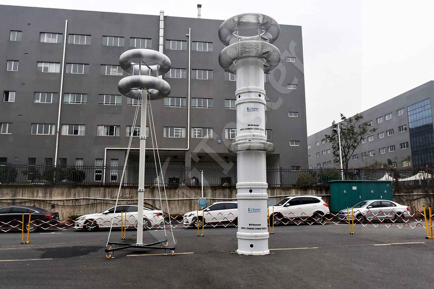
ZCVF-A series frequency conversion series resonant AC withstand voltage device is suitable for AC withstand voltage test of transformer, circuit breaker, switch, GIS system, cable, bushing, insulator and other equipment. It has the functions of high voltage over-voltage protection, low voltage over-current protection, detuning protection, zero position protection, flashover protection, emergency shutdown, under-voltage protection and so on. It not only meets the requirements of equipment test conditions for high voltage and small current, but also meets the requirements of equipment test conditions for low voltage and large current, and has a wide application range.
Kvtester Electronics Technology Co.,Ltd. is a high-tech enterprise specializing in power testing, testing, research and development, production, and sales of testing equipment. It has been engaged in the electrical testing industry for many years, and its products are of high quality. We welcome customers to come and purchase. Service hotline: 0086-27-81778799, to learn more, visit the official website: www.kvtester.com


