The ultra-low frequency high-voltage generator is a specialized equipment used for insulation performance testing of high-voltage electrical equipment. Its core principle is to convert DC power into ultra-low frequency (usually 0.01Hz~0.1Hz) high-voltage AC signals through a low-frequency oscillation circuit, thereby reducing the size and weight of the equipment while achieving voltage withstand tests on cables, transformers, and other equipment. The following is a detailed analysis of its working principle:
1. Core circuit structure: three-stage energy conversion
The ultra-low frequency high voltage generator achieves its function through three-level energy conversion of DC, low frequency AC, and high voltage AC. The key modules include:
① DC power module
Function: Convert mains power (220V/380V) into stable DC power, providing energy foundation for subsequent circuits.
Technical implementation: Using a rectifier bridge to convert alternating current into pulsating direct current. Smooth voltage fluctuations through filtering capacitors (such as electrolytic capacitors) and output DC power with ripple coefficient ≤ 1%.
② Low frequency oscillation module
Function: Converting direct current into ultra-low frequency alternating current is the key to optimizing equipment size and weight.
Technical implementation:
Inverter circuit: A full bridge inverter is constructed using IGBT (Insulated Gate Bipolar Transistor) or MOSFET (Metal Oxide Semiconductor Field Effect Transistor) to convert DC power into high-frequency square waves (usually 1kHz~10kHz).
Low frequency filtering: High frequency square waves are filtered out through LC filtering circuits (inductance+capacitance), retaining ultra-low frequency components ranging from 0.01Hz to 0.1Hz.
Waveform control: DDS (direct digital frequency synthesis) technology is used to generate high-precision sine waves or cosine square waves, with a waveform distortion rate of ≤ 3%.
③ High voltage boost module
Function: Boost low-frequency low-voltage signals to the required high voltage for testing (usually adjustable from 0-100kV).
Technical implementation:
Improvement of power frequency transformer: Traditional power frequency transformers have a large volume due to iron core saturation problems. Ultra low frequency equipment uses nanocrystalline magnetic cores or amorphous alloy magnetic cores to reduce iron loss and hysteresis loss, reducing the transformer volume to 1/5 of power frequency equipment.
Voltage doubler rectification circuit: By connecting multiple capacitors in series (such as Cockcroft Walton circuit), the AC voltage is superimposed and boosted. For example, a 4-stage voltage doubling circuit can increase the input voltage by 4 times.
2. Key technological breakthrough: balance between volume and performance
The ultra-low frequency high-voltage generator achieves "small volume, large energy" through the following technologies:
① The physical advantage of frequency reduction
Theoretical capacity reduction: According to the capacitance charging and discharging formula Q=CU (Q is the amount of charge, C is the capacitance, and U is the voltage), at the same voltage, the lower the frequency, the fewer charging and discharging cycles per unit time, and the lower the required energy.
Power frequency comparison: 50Hz power frequency equipment needs to complete one charge and discharge within 1/50 second, while 0.1Hz equipment has an extended charge and discharge cycle of 10 seconds, with a theoretical capacity of only 1/500 of power frequency equipment.
Actual test data: Testing a 1km 35kV cable (with a capacitance of 0.15 μ F), power frequency equipment requires a capacity of 100kVA, while ultra-low frequency equipment only requires 0.2kVA.
② Innovation in magnetic materials
Nanocrystalline magnetic core: The magnetic permeability is more than 10 times that of traditional silicon steel sheets, reducing iron loss by 80%, allowing transformers to operate at higher frequencies (such as 1kHz) without saturation, thereby reducing their size.
③ Efficient heat dissipation design
Phase change heat dissipation material: Fill phase change material between IGBT module and heat sink, use its melting and heat absorption characteristics to reduce thermal resistance to 0.1 ℃/W, and avoid long-term overheating protection during testing.
Actual test data: After continuous operation for 8 hours in a high temperature environment of 45 ℃, the surface temperature of the equipment is ≤ 65 ℃, and the output voltage fluctuation is ≤ 1%.
3. Workflow: The entire chain from start-up to testing
① Parameter setting: Input parameters such as test voltage (e.g. 50kV), frequency (e.g. 0.1Hz), and time (e.g. 15 minutes) through the touch screen.
② Self checking program: The device automatically detects the grounding resistance and insulation status, and issues an alarm and locks the start button when abnormal.
③ Boosting process:
a. The DC module outputs a stable voltage to the inverter circuit.
b. The inverter circuit generates high-frequency square waves and outputs ultra-low frequency AC signals after low-frequency filtering.
c. The boost module boosts the signal to the set value and monitors the output voltage and current in real time.
④ Voltage withstand test: The test object (such as a cable) is kept at a set voltage for a specified time, and the equipment records data such as leakage current and partial discharge.
⑤ Voltage reduction and report generation: After the experiment is completed, the voltage will be automatically reduced to generate a test report containing the voltage time curve and leakage current value.
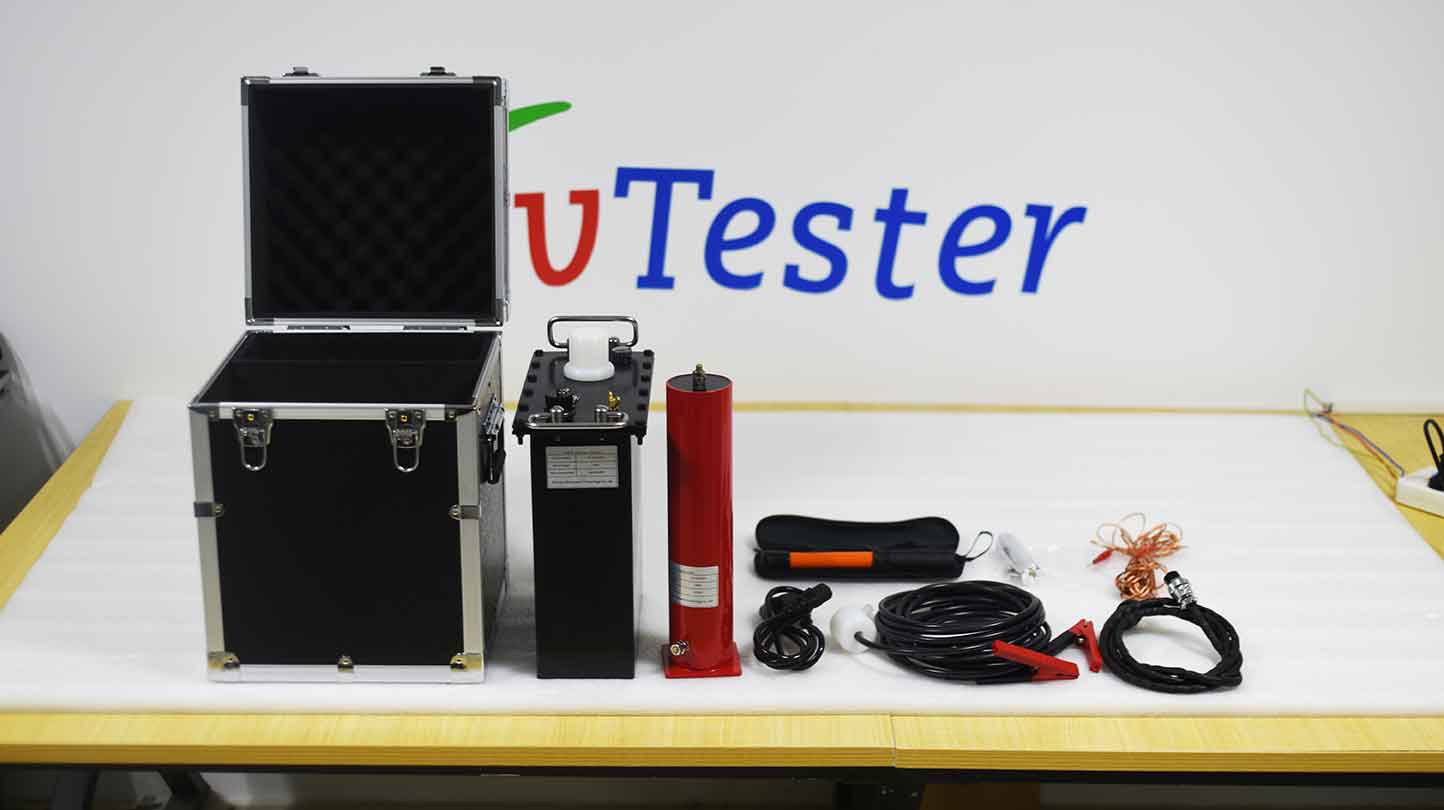
The ZC-524C ultra-low frequency and high voltage generator combines modern digital frequency conversion advanced technology and adopts microcomputer control. The boosting, lowering, measurement, and protection are fully automated, and manual intervention can be performed during the automatic boosting process. Due to its full electronic design, it has a small size, light weight, large screen LCD display, clear and intuitive display, and a printer that outputs test reports. The design indicators fully comply with the standards of the power industry and are very convenient to use.
Kvtester Electronics Technology Co.,Ltd. is a high-tech enterprise specializing in power testing, testing, research and development, production, and sales of testing equipment. It has been engaged in the electrical testing industry for many years, and its products are of high quality. We welcome customers to come and purchase. Service hotline: 0086-27-81778799, to learn more, visit the official website: www.kvtester.com


