The core working principle of a transformer winding deformation tester is based on the frequency response analysis method. By analyzing the changes in the electrical characteristics of the transformer winding at different frequencies, it determines whether its mechanical structure has undergone deformation. The following is a detailed explanation of its working principle:
1. Core Principle: Frequency Response Analysis (FRA)
① Basic Concepts
Mechanical deformation of transformer windings (such as axial/radial displacement, twisting, inter-turn short circuits, etc.) will change their distributed parameters such as inductance and capacitance, thereby affecting the frequency response characteristics of the winding.
FRA injects a low-voltage swept-frequency signal (typically 1kHz~2MHz) into the winding, measures the amplitude ratio and phase difference between the input and output signals, and generates a frequency response curve (such as a logarithmic amplitude-frequency characteristic curve).
If the winding structure is intact, the curve should be smooth and repeatable; if deformation exists, the curve will show resonance peak shifts, amplitude attenuation, or phase changes at specific frequency points.
② Physical Basis
Inductance and capacitance changes: Winding deformation leads to changes in coil spacing and inter-turn insulation distance, thereby changing the inductance (L) and distributed capacitance (C).
Resonance frequency shift: The equivalent circuit of the winding can be simplified to an RLC series or parallel resonant circuit, with a resonant frequency f0 = 1/(2π√(LC)). Deformation will change L or C, leading to a shift in f0.
Impedance characteristic changes: The impedance (Z) of a deformed winding will change significantly at specific frequencies. By measuring the impedance magnitude |Z| and phase angle θ, the degree of deformation can be analyzed.
2. System Composition
① Hardware System
Signal generator: Generates a sinusoidal swept-frequency signal (adjustable frequency range, such as 1kHz~2MHz) as the test excitation source.
Power amplifier: Amplifies the output voltage of the signal generator to an appropriate level (usually ≤10V) to drive the transformer winding.
Measurement module:
Input channel: Measures the voltage and phase of the excitation signal.
Output channel: Measures the voltage and phase of the winding response signal.
Data acquisition and processing unit: High-speed acquisition of input/output signals, calculation of amplitude ratio (dB) and phase difference (°), and generation of frequency response curves. Display and Storage Module: Real-time display of test curves, data storage to internal memory or external USB drive.
3. Key Technical Indicators and Influencing Factors
① Core Indicators
Frequency Accuracy: ≤0.01%, ensuring accurate resonance peak positioning.
Amplitude Measurement Accuracy: Better than 0.1dB, capturing subtle amplitude changes.
Phase Measurement Accuracy: ≤0.1°, for analyzing phase shifts.
Scanning Speed: Fast scanning (e.g., ≤1 second/frequency point) improves testing efficiency.
② Influencing Factors
Electromagnetic Interference: High-power equipment nearby (such as motors, welding machines) may introduce noise; shielding or keeping distance from interference sources is necessary.
Contact Resistance: Loose connections can cause signal attenuation; ensure secure connections.
Temperature Changes: Increased temperature changes winding resistance and inductance; testing should be performed in a stable environment.
Residual Charge: Sufficient discharge is required before testing to avoid interference from residual charge.
4. Deformation Judgment Methods
① Correlation Coefficient Method
Calculate the correlation coefficient (R) between the current test curve and the historical curve. If R < 0.9, deformation may exist.
② Resonance Peak Shift Method
Compare the resonance peak frequency shift (Δf). If Δf > 5%, further inspection is required.
③ Comprehensive Analysis Method
Combine methods such as oil chromatography analysis (e.g., excessive acetylene content) and infrared thermography (e.g., increased winding hotspot temperature) to comprehensively determine the cause of deformation (e.g., short circuit, overload, transportation collision).
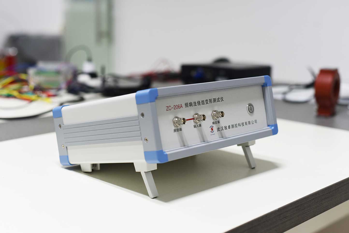
The ZC-206 transformer winding deformation tester quantifies the variation of the winding parameters in different frequency domains, determines the degree of deformation of the winding according to the trend of variation, range, range and frequency response, and then judges whether the transformer is seriously damaged or needs according to the test result. Overhaul. The device is compact and easy to operate.
Kvtester Electronics Technology Co.,Ltd. is a high-tech enterprise specializing in power testing, testing, research and development, production, and sales of testing equipment. It has been engaged in the electrical testing industry for many years, and its products are of high quality. We welcome customers to come and purchase. Service hotline: 0086-27-81778799, to learn more, visit the official website: www.kvtester.com


