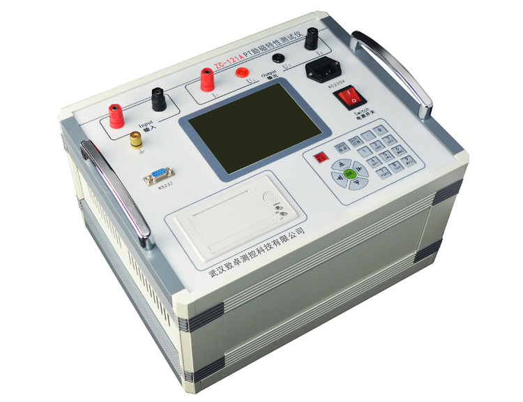
c-121a Pt excitation characteristic tester is a special instrument specially developed by our company in combination with Wuhan High Voltage Research Institute of China Electric Power Research Institute and in accordance with the latest national standard of Pt, GB / T 22071.2-2008 guide for transformer test Part 2: electromagnetic voltage transformer, and the actual needs of the transformer manufacturer 。
The instrument adopts the most advanced DSP + FPGA technology, with fast tracking and measurement speed, accurate data capture, more powerful and convenient use, and is at the leading level in China. Next, I will teach you the operation method of zc-121a Pt excitation characteristic tester.
Zc-121a Pt excitation characteristic tester
Operating instructions of zc-121a Pt excitation characteristic tester:
1. How to use keyboard
Press OK to select the current input, cancel to eliminate the wrong input, and "↑" ↓ "←" → "to move the cursor conveniently. The toggle key is the standby key. At the bottom of the keyboard are data keys 0-9. When inputting data, you can easily input data through these numbers.
2. Main interface introduction
The main interface is shown in Figure 2 and consists of 6 modules.
Fig. 2 startup interface of tester
1) Automatic test: in this test item, the automatic excitation characteristic test can be carried out according to the preset setting.
2) Manual test: manual excitation characteristic test can be carried out in this test item.
3) Test sample parameters: add, modify and delete test sample parameters.
4) Data browsing: browse and delete the stored data.
5) System setting: set the current system time and over-voltage and over-current alarm.
6) Manufacturer's setting: this function is used by the manufacturer for production commissioning.
3. Introduction to automatic test
1) Turn on the working power supply of the instrument, turn on the power switch, enter the interface diagram as shown in Figure 1 after the instrument is reset, press "↑" "↓" key to select "automatic test", then press "OK" to enter the interface of "automatic test parameter setting" as shown in Figure 3, and the right side of the interface is the wiring diagram of the test.
Figure 3 automatic test parameter setting interface
Among them:
Equipment number is used to distinguish different equipment, different test properties and times. To facilitate the search and technical management of historical data. If the corresponding number of data acquisition points have been saved in the test sample parameters, enter the number here and press "OK" to automatically complete the input of data acquisition points, without a single manual input, saving the test time.
Equipment model - model of tested object (English characters can be input);
Voltage point refers to data acquisition of various parameters based on voltage.
2) Connect the voltage regulator, instrument and tested transformer according to the wiring diagram in the interface. There is a more detailed wiring diagram at the back.
Note: the wiring process must be in accordance with the instrument, otherwise there may be burnout of the instrument or other equipment!
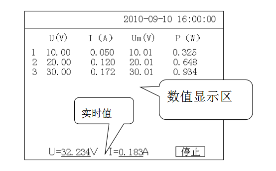
3) Set the above parameters according to the test requirements, move the cursor to select "start test", and then enter the "automatic test" interface as shown in Figure 4.
Figure 4 automatic test interface
The top part of this interface displays the current voltage frequency, the middle part is the main display area, displaying the data records that have been captured, and the bottom part is the real-time value of the current voltage and current. In this interface, adjusting the voltage regulator boosting instrument will automatically collect and display the measured values of all parameters at each test point. Until the maximum set voltage value is reached, the buzzer of the instrument will give a prompt tone to remind that the data measurement is completed. At this time, the voltage regulator should be quickly returned to zero.
Note: when the output voltage or current exceeds a certain multiple of the set maximum value due to misoperation, the instrument will prompt the over-voltage information. At this time, immediately reduce the voltage and pay attention to whether the current voltage value is within the range of the tested object.
4) After the test, the instrument interface will switch to the "automatic test result" interface as shown in Figure 5.
Figure 5 automatic test result interface
In the current interface, press the "↑" "↓" key on the keyboard to traverse the measurement results, press "save" to save the current test results to the memory of the instrument for future reference, press "print" to print the current test results through the panel printer, press "curve" key, the instrument will draw the "voltage current relationship" curve as shown in Figure 6 according to the measured data 。
Fig. 6 voltage current curve
The above is a brief summary of the operating instructions of zc-121a Pt excitation characteristic tester. Please refer to the product manual for details. If you don't know anything about Pt excitation characteristic tester, please contact our online customer service at any time~


