Measuring the DC resistance of the generator stator winding is an important method to check the integrity of the conductive circuit of the generator stator winding. The quality problems of the conductive circuit (such as welding defects, broken strands, etc.) will cause local overheating and damage the insulation. Generally, voltage drop method or DC resistance tester is used for measurement.

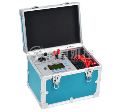
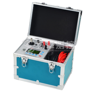
In order to meet the needs of rapid measurement, our company has developed zc-205a DC resistance tester with its own technical advantages. It uses a new power technology, with small size, light weight, large output current and other characteristics. The whole machine is controlled by single chip microcomputer, which can automatically complete self inspection, data processing, display and other functions, and has automatic discharge and discharge indication functions. The instrument has the advantages of high accuracy and easy operation, which can realize the fast measurement of the direct resistance of the transformer.
Here's how to measure the DC resistance of generator stator winding:
1、 Measurement method
(1) Before the test, discharge the stator winding of the generator to the ground.
(2) The DC resistance of each phase (or branch) winding shall be measured separately for comparison.
(3) When measured in cold state, the difference between the surface temperature of winding and the surrounding air temperature shall not be greater than ± 3 ℃. When measuring the temperature, multiple alcohol thermometers shall be used, respectively placed on the wedge between the teeth, in the ventilation hole and the end of the winding, and the average value shall be taken.
(4) When the voltage drop method is adopted, the current into the winding shall not be greater than 20% of the rated current.
(5) The length and section of each phase (or branch) lead shall be measured, and the lead resistance shall be calculated according to the lead material resistivity. When calculating the DC resistance of each phase (or branch), the lead resistance shall be deducted. After the error caused by the different lead length is corrected, the differences between the phases and the initial measurement value shall be compared.
(6) When measuring with zc-205a DC resistance tester, the current terminals (C1, C2) and potential terminals (P1, P2) of zc-205a DC resistance tester must be respectively connected to the head and tail ends of generator stator winding.
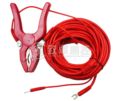
(7) The test leads shall be as short and thick as possible, and have good contact with the outgoing end of the generator stator winding.
(8) In comparison, it should be converted to the same temperature. Calculated according to formula (1-2)
R2=R1(T+t2)/(T+tl) (1-2)
Where R2 - DC resistance at T2;
R1 -- DC resistance at T1;
T -- material coefficient of copper (t = 235).
The above is a simple measurement method of DC resistance of generator stator winding. Do you understand? If you don't understand or have other questions you need to understand, you can always consult our customer service.


