CTP-1000B variable frequency transformer tester is a new generation of CT and PT testing instrument developed on the basis of traditional voltage transformer volt ampere characteristic tester based on voltage regulator, voltage booster and current transformer, after widely listening to users' opinions, after a lot of market research and in-depth theoretical research. The device adopts high-performance DSP and FPGA, and advanced manufacturing technology to ensure stable and reliable product performance, complete function, high degree of automation, high test efficiency and is in the leading level in China. It is a professional test instrument for transformer in power industry.
-
The wiring steps of current transformer test are as follows
Step 1: according to the description of CT test items described in Table 1, conduct wiring according to figure 1 or figure 2.
Table 2.5 Description of CT test items
|
Resistance |
excitation |
transformation ratio |
load |
description |
wiring diagram |
|
√ |
|
|
|
Measurement of CT secondary winding resistance and excitation |
Figure 2.1 |
|
√ |
√ |
|
|
|
Figure 2.1 |
|
√ |
|
√ |
|
|
Figure 2.1 |
|
√ |
√ |
√ |
|
|
Figure 2.1 |
|
|
|
|
√ |
|
Figure 2.2 |
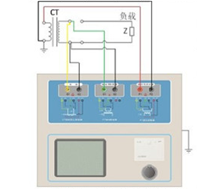
Figure 2.1 Connection mode of CT DC resistance, excitation and transformation ratio test
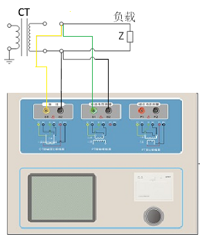
Figure 2.2 Connection mode of CT secondary load test
Step 2: other windings of the same CT are open circuit, the primary side of CT should be grounded, and the equipment should also be grounded.
Step 3: turn on the power and prepare for parameter setting.
-
Test parameter setting of current transformer
The test parameter setting interface is shown in Figure 3.
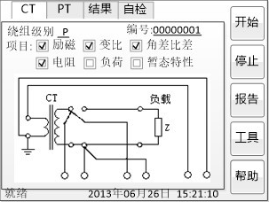
The parameter setting steps are as follows:
Rotate the mouse to switch the cursor and select the test item to be carried out. When the cursor stays at a certain test item, the screen displays the parameter settings related to the test item; when the cursor leaves the test item, the screen displays the wiring diagram corresponding to the selected test item.
The parameters that can be set are as follows:
(1) Number: input the number of this test, which is convenient for printing, saving, management and searching.
(2) Rated secondary current Isn: the rated current at the secondary side of current transformer, generally 1A and 5A.
(3) Grade: the level of the tested winding. For CT, there are 8 options, such as P, TPY, metering, PR, PX, TPS, TPX, TPZ.
(4) Current temperature: the winding temperature during the test. Generally, the air temperature during the test can be input.
(5) Rated frequency: optional values are: 50 Hz or 60 Hz.
(6) Maximum test current: generally, it can be set as the rated secondary current value. For TPY class CT, it can be set to 2 times of the rated secondary current value. For class P CT, if it is 5P40 and rated secondary current is 1A, then the maximum test current should be set as 5% * 40 * 1A = 2A; if it is 10P15 and rated secondary current is 5A, then the maximum test current should be set as 10% * 15 * 5A = 7.5A.
If you want to see the following results, you need to set the basic parameters accurately (it is recommended that you set them).
(1) Turn ratio error, ratio difference and phase difference
(2) Accurate calculation of limit electromotive force and its corresponding compound error
(3) The accurate limit value of the safety factor and the safety factor of the instrument
(4) Measured transient area coefficient, peak instantaneous error and secondary time constant
For different levels of CT, the parameter settings are also different, as shown in Table 2.
|
Parameter |
Description |
P |
TPY |
Metering |
PR |
PX |
TPS |
TPX |
TPZ |
|
Rated primary current |
Used to calculate the exact actual current ratio |
√ |
√ |
√ |
√ |
√ |
√ |
√ |
√ |
|
Rated load power factor |
Rated load on the rating plate with power factor of 0.8 |
√ |
√ |
√ |
√ |
√ |
√ |
√ |
√ |
|
Rated accuracy limit factor K |
The default value on the name plate is 10. It is used to calculate the limit electromotive force and its corresponding compound error |
√ |
|
|
|
|
|
|
|
|
Rated symmetrical short circuit current coefficient Kssc |
The default value on the name plate is 10. It is used to calculate the limit electromotive force and the corresponding peak instantaneous error |
|
√ |
|
|
|
√ |
√ |
√ |
|
Primary time constant |
default: 100ms |
|
√ |
|
|
|
|
√ |
√ |
|
Secondary time constant |
default: 300ms |
|
√ |
|
|
|
|
|
√ |
|
Work cycle |
C-t1-0 or C-t1-0-tfr-C-t2-0,
Default : C-t1-0 cycle |
|
√ |
|
|
|
|
√ |
|
|
t1 |
First current passing time, Default: 100 ms |
|
√ |
|
|
|
|
√ |
|
|
ta11 |
Time for primary flow to maintain accurate limits, Default: 40ms |
|
|
|
|
|
|
|
|
|
tfr |
Time delay for first opening and reclosing, Default: 500ms. Select C-t1-0-tfr-C-t2-0 cycle to display |
|
√ |
|
|
|
|
√ |
|
|
t2 |
Second current passing time, default: 100. Select C-t1-0-tfr-C-t2-0 cycle to display |
|
√ |
|
√ |
|
|
√ |
|
|
ta12 |
Time for secondary flow to maintain accurate limits, Default: 40ms.
Select C-t1-0-tfr-C-t2-0 cycle to display. |
|
√ |
|
|
|
|
√ |
|
|
Safety factor of rated instrument |
The default value on the name plate is 10. It is used to calculate the limit electromotive force and its corresponding compound error |
|
|
√ |
|
|
|
|
|
|
Rated calculation coefficient |
|
|
|
|
|
√ |
|
|
|
|
Rated inflection point potential Ek |
|
|
|
|
|
√ |
|
|
|
|
le corresponding to EK |
|
|
|
|
|
√ |
|
|
|
|
Area coefficient |
|
|
|
|
|
|
√ |
|
|
|
Rated Ual |
Rated equivalent secondary limiting voltage |
|
|
|
|
|
√ |
|
|
|
Ial corresponding to Ual |
|
|
|
|
|
|
√ |
|
|
-
Step 5: select the start button on the right to test.
2. Test results of frequency conversion transformer comprehensive tester
The results are shown in Figure 4.
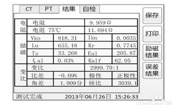
Figure4 Test result interface
For different levels of CT and selected test items, the test results are also different, as shown in Table 3.
Table 3
|
Test Result |
Discription |
P |
TPY |
Metering |
PR |
PX |
TPS |
TPX |
TPZ |
|
Load |
Measured load |
Unit: VA, CT secondary side measured load |
√ |
√ |
√ |
√ |
√ |
√ |
√ |
√ |
|
Power factor |
measured load power factor |
√ |
√ |
√ |
√ |
√ |
√ |
√ |
√ |
|
Impedance |
Unit: Ω, measured impedance of CT secondary side |
√ |
√ |
√ |
√ |
√ |
√ |
√ |
√ |
|
resistance |
Resistance(25℃) |
Unit: Ω, resistance at current temperature |
√ |
√ |
√ |
√ |
√ |
√ |
√ |
√ |
|
Resistance(75℃) |
R, Unit: Ω, Converted to the resistance at 75℃ |
√ |
√ |
√ |
√ |
√ |
√ |
√ |
√ |
|
Excitation |
Inflection point voltage and inflection point current |
Unit: V and A respectively. According to the standard definition, when the inflection point voltage increases by 10%, the inflection point current increases by 50% |
√ |
√ |
√ |
√ |
√ |
√ |
√ |
√ |
|
Unsaturated inductance L |
Unit: H, average inductance of linear section of excitation curve |
√ |
√ |
√ |
√ |
√ |
√ |
√ |
√ |
|
Remanence coefficient K |
ratio of residual flux to saturation flux |
√ |
√ |
√ |
√ |
√ |
√ |
√ |
√ |
|
Quadratic time constant T |
Unit: s, time constant of CT secondary connection with rated load |
√ |
√ |
√ |
√ |
√ |
√ |
√ |
√ |
|
Limit electromotive force E |
Unit: V, limit electromotive force calculated according to CT rating plate and 75 ℃ resistance |
√ |
√ |
√ |
√ |
|
|
√ |
√ |
|
Composite error ε |
Composite error under the limit electromotive force E or rated inflection point potential EK |
√ |
|
√ |
√ |
√ |
|
|
|
|
Peak instantaneous error ε |
Peak instantaneous error under the limit electromotive force E |
|
√ |
|
|
|
|
√ |
√ |
|
Accuracy limit coefficient |
Accurate limit coefficient measured |
√ |
|
|
√ |
|
|
|
|
|
Instrument safety factor |
Measured instrument safety factor |
|
√ |
|
|
|
|
|
|
|
Symmetrical short circuit current multiple Kssc |
Measured symmetrical short circuit current multiple |
|
√ |
|
|
|
√ |
√ |
√ |
|
Transient area coefficient |
Actual transient area factor |
|
√ |
|
|
|
|
√ |
√ |
|
Calculation coefficient Kx |
Actual calculation coefficient |
|
|
|
|
√ |
|
|
|
|
Rated inflection point potential Ek |
Measured excitation dia corresponding to rated inflection point potential |
|
|
|
|
√ |
|
|
|
|
Ie corresponding to Ek |
|
|
|
|
|
√ |
|
|
|
|
Rated Ual |
rated equivalent secondary limiting voltage |
|
|
|
|
|
√ |
|
|
|
Ial corresponding to Ual |
Measured excitation current corresponding to rated equivalent secondary limiting voltage |
|
|
|
|
|
√ |
|
|
|
Error curve |
5% (10%) error curve |
√ |
√ |
|
√ |
√ |
√ |
√ |
√ |
|
Transformer Ratio |
Transformer Ratio |
Actual current ratio at rated load |
√ |
√ |
√ |
√ |
√ |
√ |
√ |
√ |
|
Turn ratio |
Actual turn ratio of secondary winding to primary winding under test |
√ |
√ |
√ |
√ |
√ |
√ |
√ |
√ |
|
Ratio difference |
Current error under rated load |
√ |
√ |
√ |
√ |
√ |
√ |
√ |
√ |
|
phase difference |
Phase difference at rated load |
√ |
√ |
√ |
√ |
√ |
√ |
√ |
√ |
|
Polarity |
There are two kinds of polarity relations between CT primary and secondary, i.e., homopolarity/ -(reduced polarity) and reverse polarity/+ (additive polarity) |
√ |
√ |
√ |
√ |
√ |
√ |
√ |
√ |
|
Turn ratio error |
Relative error between measured turn ratio and rated turn ratio |
|
|
|
|
√ |
√ |
|
|
|
Standard error |
Table of current error and phase error of international inspection current point under rated load and lower limit load |
|
|
√ |
|
|
|
|
|


