ZC-601 three-phase electricity tester is a kind of intelligent instrument which can diagnose whether the measurement of low-voltage electric energy metering device is normal, and has the functions of intelligent electric energy meter calibration and power consumption monitoring, It is an intelligent instrument with high cost performance.
The tester adopts hand-held structure, small size, light weight and easy to use; the input and output adopts isolation technology, which makes the instrument more safe and reliable; the metering device and instrument are designed without disconnection during field test; the powerful background management and analysis software is convenient for data management.
Parameter setting method
In the parameter setting screen, the meter constant, number of calibration cycles, CT ratio, calibrator and meter number, user name and clock can be set. You can move the cursor to the position to be set by using the "↑↓" key, select different bits of this option with "←→" key, and press the required number key.
For working mode, input mode, range selection of clamp type transformer and accuracy of electric meter, the cursor can be moved to the position that needs to be modified by using the "↑↓" key, and different contents can be selected with "←→" key. After setting, press "confirm" key to complete parameter setting and return to the main menu.
Input method of parameters
Verifier, user name: you can input upper and lower case letters, numbers and special characters, and the input type can be switched with the "switch" key.
Meter constant, number of calibration turns, CT ratio, clock setting: only digital can be input.
Table number: you can input upper and lower case letters, numbers and special characters
Note: only when the "confirm" key is pressed, the system will recognize the modification of the data, otherwise, the modified data will not be saved.
1. The interface of "basic parameters" is shown in Figure 1
(1) - display the current measured voltage and current values.
(2) - display power factor and frequency
(3) - display the angle value of voltage and current
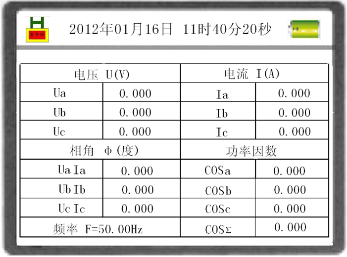
Figure 1 basic parameters
2. The "power" interface is shown in Figure 2
(1) - displays the active power currently measured.
(2) - display the current measured reactive power.
(3) - display the current measured apparent power.
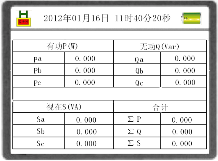
Figure 2 power
3. "CT ratio" interface (optional), as shown in Figure 3:
The instrument calculates the current transformer ratio and displays the ratio and polarity. "+" stands for the same polarity and "-" stands for opposite polarity.
When the current transformer is measured from one side of the current clamp, it should be noted that there is no sign of the current transformer flowing into the transformer. In the measurement, the small range clamp current transformer of each phase is used to measure the transformation ratio and polarity of each phase corresponding to the large range current transformer of this phase.
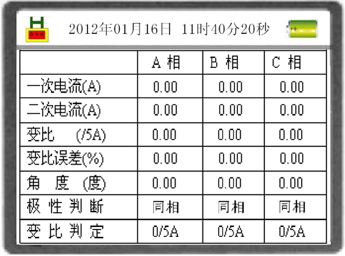
Figure 3 CT ratio
4. Press [5 / mno] in the main menu to enter the "vector graph" interface, as shown in Figure 4
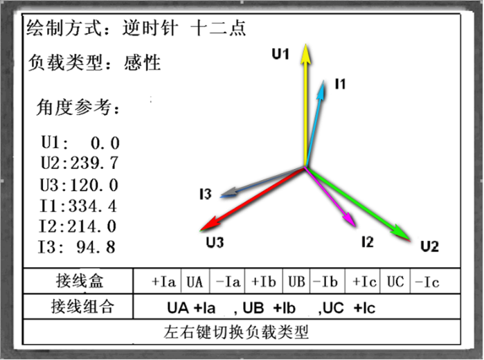
Fig. 4 vector diagram
(1) Vector graph display
The screen displays the current time vector diagram and locks automatically; the screen under this screen shows the result of wiring identification. The vector diagram only reflects the phase relationship between voltage and current, but not the amplitude relationship.
When the circuit is broken or there is no signal, it will prompt the disconnection information, and the vector diagram will not be displayed.
(2) Distinguish wiring
This function is used to judge the wiring of three-phase three wire metering circuit. The instrument can distinguish 48 common wiring modes (excluding reverse connection of voltage transformer, and excluding incoming B-phase current when measuring three-phase ).
The user can select the reference vector graph according to the load, and the left and right keys can switch the load type. The voltage and current grouping display, such as UA + Ia, UB + Ib, UC + Ic, indicates that U1 is connected with UA, I1 is connected with forward Ia, U2 is connected with UB, I2 is connected with forward Ib, U3 is connected with UC, I3 is connected with forward Ic, and positive and negative signs indicate current polarity.
(3) The following conditions must be met in connection identification:
The inductive load 0℃ < φ < 60℃ (0.5L < cos φ < 1)
Capacitive load – 36℃ < φ < 0℃ (0.8C < cos φ < 1)
Current load Ia, Ic > clamp current transformer range × 10%
5. The "error calibration" interface is shown in Figure 5
(1) In this interface, the verification pulse can be received for verification. The electric energy is the accumulated electric energy of the tester within the verification turns.
(2) When the input mode is automatic, the instrument will calculate the error once after collecting the set number of validation circles. When the input mode is manual, press the "manual" key to start the acquisition for the first spot and press the "manual" key for the last spot to finish the acquisition and calculate the error.
(3) Data storage
After the verification results are displayed, press the "confirm" key to store the current parameters.
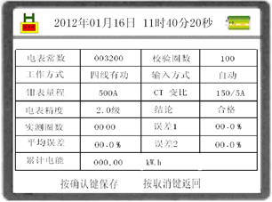
Figure 5 error calibration
6. The interface of "check constant" is shown in Figure 6
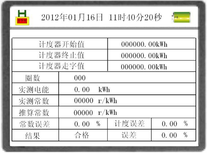
Figure 6 check constant
Connect the manual switch or photoelectric (pulse) head, select the "check constant" function, then record the initial value of the watt hour meter, input the initial degree into the instrument, and press the "confirm" key, the instrument can now receive the signal of the photoelectric head, and the electric energy starts to calculate.
When the accumulated electric energy is enough, input the end value of the watt hour meter and press the "confirm" key, and the instrument will automatically calculate the electric energy of the meter's font. Check with the accumulated electric energy of the instrument, and the check result is displayed at the bottom of the screen.
This instrument provides two functions: checking the meter and calculating the constant of electric meter


