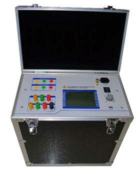
ZC-208 transformer DC resistance ratio loss characteristic comprehensive tester is the latest professional transformer test equipment launched by our company, which can be used for the transformation ratio and DC resistance test of various transformers in power system, especially suitable for the test of Z-winding transformer, rectifier transformer and balance transformer. The instrument adopts large screen liquid crystal display, full Chinese menu, friendly man-machine interface, perfect function and convenient operation. It is an ideal instrument for measuring DC resistance, transformation ratio, group, polarity and angle of transformer for power system, transformer manufacturer and railway electrical system.
In addition, the device supports Bluetooth wireless communication and can realize wireless operation and data analysis functions with professional data analysis software of upper computer.
 1. How to use the rotating mouse
In the digital input mode, turn left or right to change the number, press down to confirm the current selection and shift. When the menu selection lost, turn left or right to move the cursor, and down to confirm (OK).
2. Introduction of main interface
The main interface is shown in the figure below, which is composed of four modules.
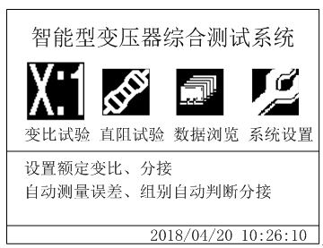
Boot main interface
1. Transformation ratio test: measure the transformation ratio, error and phase shift angle of single-phase transformer and three-phase transformer.
2. Resistance test: measure DC resistance of single-phase and three-phase transformers.
3. Data browsing: browse and delete the stored data.
4. System settings: set the current system time, system parameters and system upgrade.
3. Introduction to transformation process
1. Conduct correct wiring according to the corresponding wiring diagram in the operation manual.
2. Select the transformation ratio test in the main interface to display the transformation ratio test setting interface, as shown in the following figure:
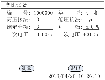
Ratio test setting page
This page saves the setting value of the last test, check and modifies the setting value in this page to make it consistent with the current test transformer.
Number: the number of the tested object, which is used for the management of the tested object and the preservation and identification of the test record.
Type: the type of the tested object, including three-phase, single-phase, Scott and reverse Scott transformers, and single-phase for voltage transformer ratio test.
High voltage and low voltage connection: this option will appear when three-phase transformer is selected. It is only used as an auxiliary item for displaying and printing groups and does not affect the test results.
Rated tapping: it means the rated tapping gear of transformer, which is used to automatically judge the current test gear.
Each gear: the voltage regulation percentage of transformer, which is used to automatically judge the current test gear.
Primary voltage and secondary voltage: the transformer is at the rated primary and secondary voltage. If this setting item is set incorrectly, it will affect the test result of comparison difference. Please refer to the transformer name plate when setting the above parameters.
1. In the above figure, select "measure" with the cursor, and press the confirm key to enter into the following automatic step-up page of variable ratio test:
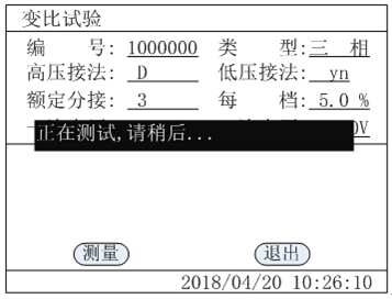
Automatic boost page of transformation ratio test
In this step-up interface, the instrument will automatically rise to the appropriate voltage according to the transformation ratio of the transformer, and test the transformation ratio, error and phase shift angle. This process will be completed within 10 seconds. If there is an error in the test process, the error message will be prompted, and the test result page will appear as shown in the figure below.
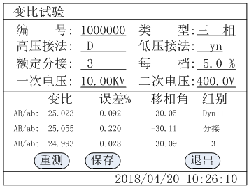
Measurement result interface
The "save" on the page saves the current result to the random memory;
Note: the error at this time is the error between the measured transformation ratio and the current transformation ratio.
In the figure above, press "retest" to retest the tested object, and press "exit" to return to the main interface of the previous system function.
4. Introduction of DC resistance test process
1. Conduct correct wiring according to the corresponding wiring diagram in the operation manual.
2. Select the transformation ratio in the main interface to display the ratio test setting interface, as shown in the following figure:
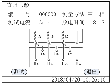
Direct resistance test setting interface
This page saves the setting value of the last test. Check and modify the setting value in this page to make it consistent with the current test transformer
Number: the number of the tested object, which is used for the management of the tested object and the preservation and identification of the test record.
Test method: single phase, two-phase and three-phase are available;
Test current: there are auto, less than 5mA, 40mA, 200mA, 400mA, 1A, 5A and 10A gears, which are selected according to the corresponding range of each current gear.
Discharge time: the waiting discharge time after each phase test.
After setting, press "test" to enter the test interface as shown in the following figure:
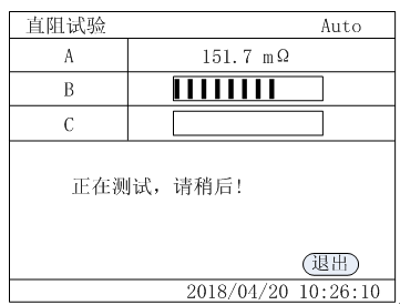
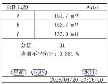
Direct resistance test interface
The following points should be noted during the test:
1. When measuring the reverse tap changer of no-load tap changer, it is necessary to wait for the end of discharge and stop the alarm sound before switching off the tap point.
2. Before removing the wire, be sure to wait until the discharge is over and the alarm stops before removing the wire.
3. When selecting the current, it is necessary to refer to the range in the technical index column, and do not exceed the range or under range. When over range is used, the stability of test results is poor even if the current cannot reach the pre-set value. Under range, the current is too small and the data is unstable for large capacity transformer. When these two states appear, confirm the range and select the appropriate range for testing.
After all three-phase tests are completed, the DC resistance test results as shown in the following figure are displayed: