ZC-602 distribution transformer area (Branch) identification instrument is composed of host, handheld extension and related accessories. The communication between host and handheld extension adopts low-frequency zero crossing communication technology and pulse current detection technology, which can accurately identify station area, phase and branch under the circumstance of adjacent substations share high voltage, common ground and common cable trench.
 Instructions for host
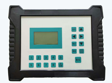
The host is shown in the following figure:
Wiring instructions
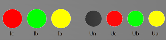
Figure 1 (front panel)
Voltage input: A phase voltage input Ua yellow, B phase voltage input Ub green, C phase voltage input Uc red, zero line input Un black.
Current input: phase A current input Ia yellow, phase B current input Ib green, and phase C current input Ic red. Under shutdown state, connect one end of the voltage test line to Un, Ua, Ub, Uc terminals on the back panel of the instrument according to black, yellow, green and red, and the other end of the voltage test line (clamp can be installed) is clamped to Un, Ua, Ub and Uc of the transformer outlet.
The clamping mode of clamp ammeter should be selected according to the site environment and use needs. The following modes can be selected:
Branch test with 500A clamp meter
As shown in the figure, except for Ua, Ub, Uc and Un connected with voltage, clamp 500A clamp ammeter to branch zero line of branch to be tested (or clamp branch A, B, C three-phase lines at the same time).
After connecting the line, start the machine and change the measuring range to "zero sequence current".

Fig. 2 Schematic diagram of branch test with 500A clamp table
500A clamp table was used to test the relationship of station area ownership
As shown in the figure, first connect Ua, Ub, Uc, Un voltage lines under shutdown condition, and then clamp A, B, C three-phase clamp ammeter on A, B, C three-phase low-voltage copper bar or low-voltage cable of low-voltage main outlet of transformer.
After connecting the wire, start the machine and modify the measuring range to "phase current 500A".
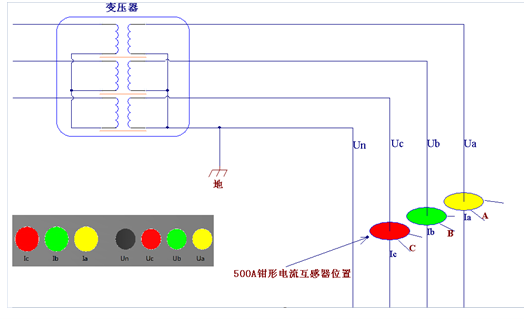
Fig. 3 Schematic diagram of 500A clamp table for bench area ownership test
5A clamp table was used to test the relationship of station area ownership
As shown in the figure, if it is not convenient to clamp the low-voltage copper bar or cable with 500A clamp meter on site, and if the low-voltage total copper bar or cable is equipped with current transformer for metering, three 5A clamp meters can be used for field acquisition of current signal.
After connecting the wire, start the machine and change the measuring range to "phase current 5A".
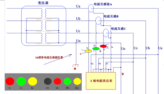
Fig. 4 Schematic diagram of station area ownership test with 5A clamp table
Attentions:
During branch test, the current clamp must clamp the zero line of each branch correctly. This is illustrated in the figure below.
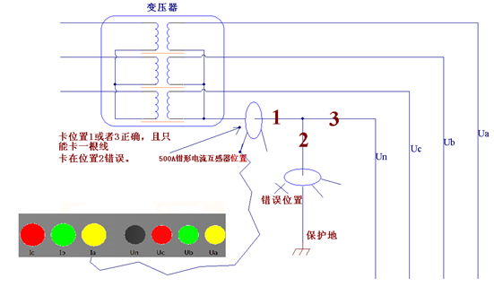
Figure 5 Schematic diagram of correct clamping of branch zero line clamp table
Note: when wiring the voltage test line, connect the zero line first and then the fire line and the phase must be corresponding, otherwise the measurement accuracy will be affected.


