3、 Strong overload capacity
4、In the case of load, steplessly, smooth and continuous regulation of output voltage can work for a long time.
Basic principles and application:
The structure of the Variable transformer is similar to the general wire-wound asynchronous motor, but because it often works under the braking state, its action principle is actually similar to the transformer action principle. The Variable transformer is equipped with a worm gear drive mechanism to cause angular displacement of the rotor. Or make the rotor brake. When the relative Angle position of rotor is changed, the alternating chain flux between stator winding and rotor winding is changed for single-phase Variable transformer. For the three-phase Variable transformer, the induction potential phase on the tator winding and rotor winding is changed, and the output voltage is alsovsmoothed and stepless by coupling the circuit.
Operating environment and working conditions of the Variable transformer:
(1). Elevation is not exceeding 1000m;
(2). The surrounding medium temperature is not higher than + 40 ℃ not less than 25 ℃.
(3). Air relative humidity shall not exceed 85%;
(4). In an environment free from chemically aggressive gases and steam;
(5). In gas free from explosive risk;
(6). Where it is free from rainwater invasion;
(7). Cannot be used in parallel.
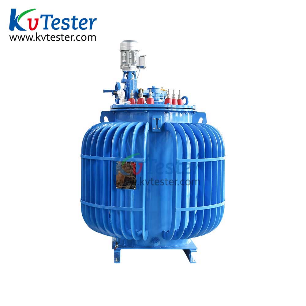
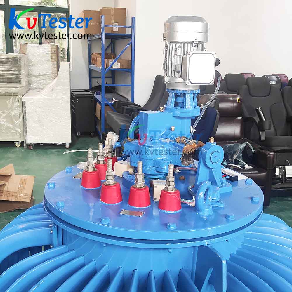
Structural characters:
The structure of the Variable transformer can be divided into three parts:main body, cooling oil tank and transmission control.
(1) Its main body is composed of stator, wire-wound rotor, panel andbase, like wire-wound asynchronous motor, and is vertically installed. The windings of the Variable transformer are generally: three-phase is two-layer short pitch overlapping windings; Single phase is single layer concentric winding.
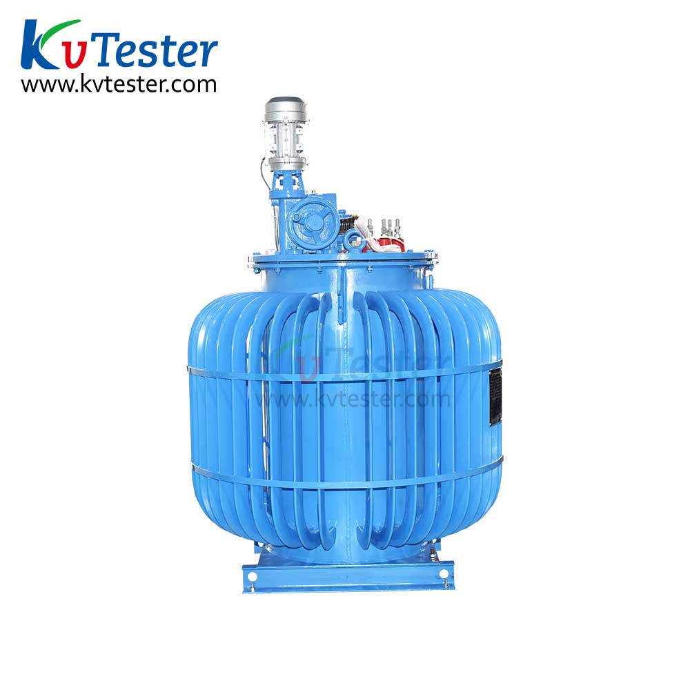
(2) Transmission control is divided into two types: electric motor type or manual type. Manual type is limited to less than 10KV. And clearly marked with the "up, down" rotation direction indicator.
(3) Electric motor type and manual dual-use type’s transmission device is composed of two pairs of worm gear, worm, clutch (flat gear), hand wheel, transmission motor (servomotor, which is a standard three-phase asynchronous motor), travel switch (limiter) and limit device.The first pair of worm and worm gear is connected with the drive motor by an elastic coupling, which is used to reduce the motor speed and drive the second pair of worm and worm.The electric drive generally controls the motor on the Variable transformer to make positive and reverse rotation through the button of the remote control equipment, thus changing the load voltage of the Variable transformer. The hand wheel drive is connected with the second pair of worm by a flat gear and a long key guide. Hand wheel drive is often used to fine adjust the voltage or to ensure the Variable transformer to adjust normally when the motor fails. From hand wheel drive to electric drive or vice versa, the clutch (flat gear) can be pushed into the coupling mechanism to achieve that. The travel switch is used to limit the load voltage of the Variable transformer in the maximum and minimum two limit positions when the motor power is automatically cut off, the limiter is to limit the rotor according to the specified mechanical Angle of rotation. In order to prevent overload or short circuit at the load end, the drive control mechanism is easy to be damaged, safety bolts are provided, which are cut off in case of over load or short circuit.
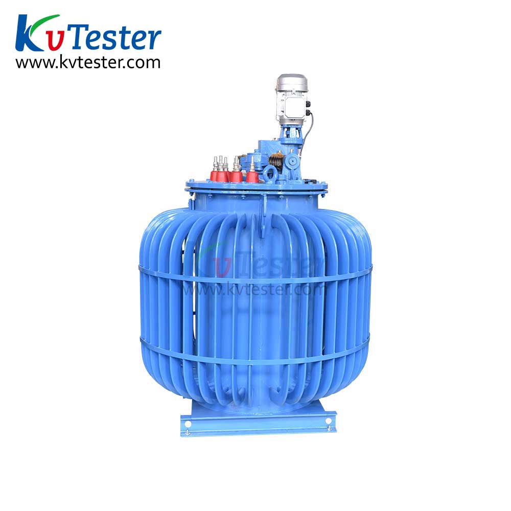
(4) Manual type transmission device is composed of worm gear, worm gear, hand wheel and limiting device. When the load voltage of the Variable transformer needs to be adjusted, then the hand wheel will drive the worm and worm wheel to achieve the purpose of voltage regulation.The retainer is only used to restrict the rotation of the rotor at specified mechanical angles.
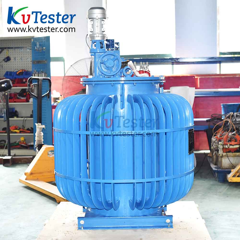
(5) The cooling tank structure of the Variable transformer is similar to that of general power transformers.
(6) Oil injector and temperature measuring device etc. are installed on the panel.