Grounding resistance is an important parameter used to measure whether the grounding state is good. It is the resistance encountered when the current flows from the grounding device to the ground and then flows through the ground to another grounding body or spreads to a distance. It includes the resistance between the grounding wire and the grounding body itself, the contact resistance between the grounding body and the ground, and the resistance between two grounding bodies or the ground resistance from the grounding body to an infinite distance. The size of the grounding resistance directly reflects the good degree of contact between the electrical device and the "ground", and also reflects the scale of the grounding network.
1、 Analysis of reasons for inaccurate measurement:
1. Due to the fact that the grounding resistance tester tests the grounding resistance of the grounding body through the emission and reception of current by the iron brazing rod, mutual interference will occur when the distance between the two iron brazing rods and between the two brazing rods and the grounding body is too close, resulting in errors. Therefore, during measurement. The grounding body, voltage pole, and current pole are arranged in sequence, with three points in a straight line and 20 meters away from each other.
2. Under the condition of "public ground", the measured Earth electrode has a certain ground voltage generated by the grounding device to the property due to poor insulation or short circuit of the equipment, which makes the reading unstable during measurement. At this time, the power should be cut off for detection, or the place with a disconnection card should be disconnected for detection to avoid the impact of ground voltage on the detection.
3. The grounding depth of the iron drill should be greater than 1/4 of the length of the iron drill, otherwise testing errors will occur. Therefore. During testing, the iron drill should be drilled as deep as possible.
4. When detecting high-rise buildings, using wires that are too long or too thick can increase line resistance and induced voltage, resulting in measurement errors. At this point, wires with relatively low line resistance should be used to minimize measurement errors as much as possible.
5. Poor contact. When the object being tested is rusted or the detection line is broken, it will be found that there is a phenomenon of disconnection or high resistance during the detection. At this point, rust should be removed first. If it still cannot be ruled out, use the resistance range of a multimeter to check the continuity of the detection wire.
6. When there are materials such as bedding soil or sand in the measured area, measurement errors may occur due to the different electrical resistivity of the upper and lower layers of soil. At this point, a deep iron drill should be used to make it fully contact with the soil under the cushion layer or avoid the cushion layer, so as to reduce measurement errors.
7. Inaccurate measurement due to potential differences or strong magnetic fields on the surface. At this point, it is necessary to try to stay away from places with large potential differences or strong magnetic fields. If unavoidable, the detection line should be relatively shortened to reduce measurement errors.
8. When the grounding device and metal objects such as metal pipelines being detected are buried in a complex manner, it may change the current direction of each pole of the measuring instrument, causing poor or unstable measurement. At this point, it is necessary to first understand the layout of the grounding body and metal pipeline, and select areas with relatively small impact for measurement.
9. Factors such as product quality issues with the instrument, failure to strictly follow the instructions, failure to repair the grounding resistance tester in a timely manner, inaccurate or long-term lack of identification can also cause measurement errors.
2、 Solution
After understanding the reasons for the inaccurate reading of the grounding resistance test, the editor will provide a detailed explanation of the solutions for the unqualified grounding resistance test.
1. Method of burying copper plates
a. Dig a deep pit of 250cm * 150cm * 300cm near the computer room, sprinkle some sodium chloride at the bottom of the pit, and bury it in a copper plate (1500mm * 600mm * 3mm). The pit depth is subject to water exposure, but at least greater than 200cm.
b. Weld the flat steel (30mm * 3mm) and copper plate together with copper solder, and lead them out to the ground as leads.
c. Weld the galvanized flat steel and the flat steel lead together, leading out at a distance of 2m from the wall.
d. The resistance value of the grounding grid measured by the tester is less than or equal to 4 ohms.
e. Use a 25mm square copper core wire to firmly connect with the grounding grid lead wire through the copper wire nose and introduce it into the room.
f. Connect the signal lightning arrester ground wire and electrostatic ground wire.
2. Pile driving method
a. Install a double grounding electrode, or dig a pit to add salt and charcoal, and bury the grounding pile. Or make another grounding grid according to the system requirements or add a grounding grid in the original earthing system. Grounding resistance refers to the resistance encountered when the current flows from the grounding device to the ground and then flows through the ground to another grounding body or diffuses towards a distance. The grounding resistance value reflects the good degree of contact between the electrical device and the "ground" and reflects the scale of the grounding network.
b. Drive 4 or more 2.5m angle steels (45mm * 45mm) into the ground in a straight line near the computer room, 80cm above the ground, with each angle steel spaced 2m apart.
c. The ratio of the voltage of the grounding device to the current flowing into the ground through the grounding body. The lightning protection grounding resistance is the total resistance of the grounding body or natural grounding body to the ground, called the grounding resistance of the grounding device. Its value is equal to the ratio of the grounding device's voltage to the current flowing into the ground through the grounding body. At the same time, the grounding resistance is also a symbol to measure the level of the grounding device.
d. Use flat steel (30mm * 3mm) to weld four angle steels in series together.
e. Use galvanized flat steel (30mm * 3mm) to weld any corner of the angle steel as a ground wire lead to the wall at a distance of 2m.
f. The resistance tester measures the resistance of the grounding grid to be less than or equal to 4 ohms. Otherwise, additional piles or use a grid to solve the problem.
g. Use a 25mm square copper core wire to firmly connect with the grounding grid lead wire through a copper wire nose and introduce it indoors.
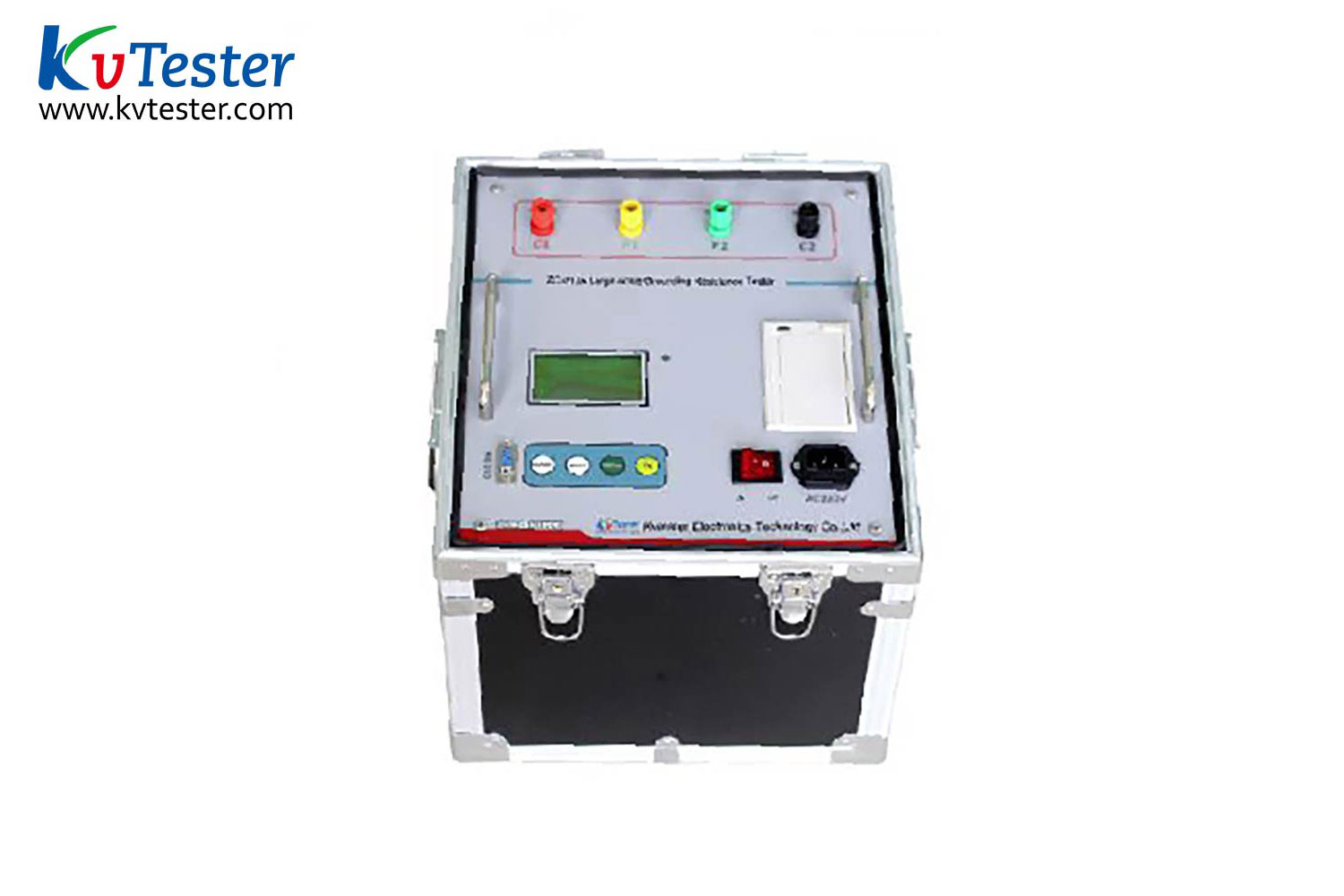
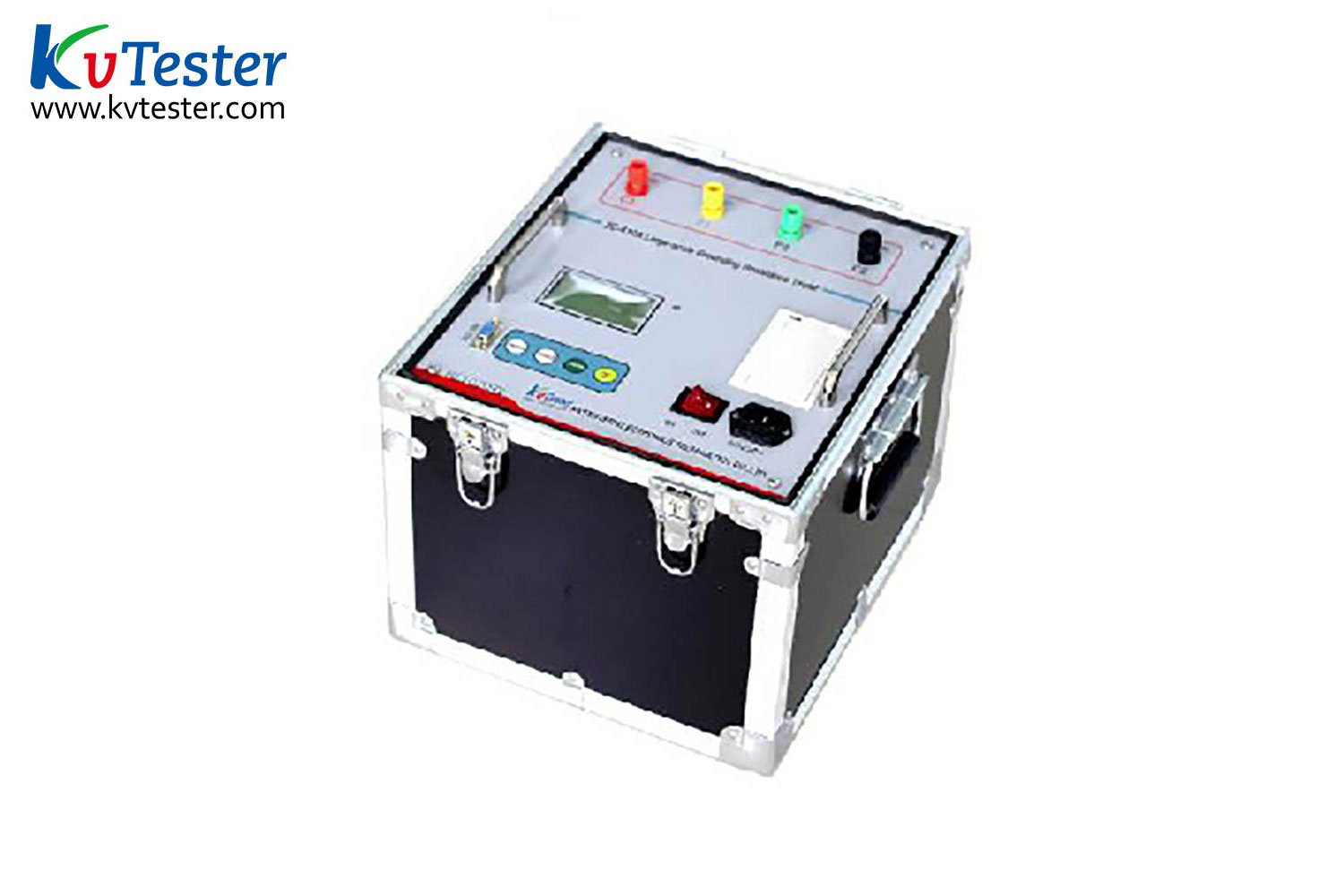
ZC-410A Large Ground Grid Grounding Resistance Tester is a specialized instrument for measuring the grounding resistance of the grounding grid and the grounding continuity between the grounding point. Adopting frequency conversion anti-interference technology and applying measures such as microcomputer processing to control the grounding impedance tester and signal processing of the grounding network, it does not require large current measurement and can accurately measure 50Hz data in a strong interference environment of the substation. This effectively solves the anti-interference problem during the testing process, simplifies the experimental operation process, improves the accuracy and accuracy of the testing results, and greatly reduces the labor intensity and testing cost of the testing personnel. The instrument can simultaneously measure grounding impedance and grounding resistance, which can more accurately reflect the actual characteristics of the grounding grid.
Kvtester Electronics Technology Co.,Ltd. is a high-tech enterprise specializing in power testing, testing, research and development, production, and sales of testing equipment. It has been engaged in the electrical testing industry for many years, and its products are of high quality. We welcome customers to come and purchase.


