There are usually several measurement methods for grounding resistance testers: two wire method, three wire method, four wire method, single clamp method, and double clamp method, each with its own characteristics. In actual measurement, the correct method should be chosen as much as possible to ensure accurate measurement results.
1. Two line method
Condition: There must be a known good grounding. For example, PEN. The measured result is the sum of the resistance of the measured ground and the known ground. If the known ground is much smaller than the resistance of the measured ground, the measured result can be used as the result of the measured ground.
Suitable for buildings and cement floors. Seal areas where ground stakes cannot be driven.
Wiring: E+ES to receive the measured ground. H+S receives known ground.
2. Three line method
Condition: There must be two grounding rods: one auxiliary grounding rod and one detection electrode, with a distance of no less than 20 meters between each grounding electrode. The principle is to apply a current between the auxiliary ground and the measured ground. Measure the voltage drop measurement result between the measured ground and the probe electrode. This includes measuring the resistance of the cable itself.
Applicable to: ground grounding, construction site grounding, lightning ball lightning rod, QPZ grounding.
Wiring: Connect S to the detection electrode. H is connected to auxiliary grounding. Connect E and ES to the tested ground.
3. Four line method
Basically, the same three wire method eliminates the influence of measuring cable resistance on low ground resistance measurement results when replacing the three wire method for measurement. When measuring, e and es must be directly connected to the measured ground, which is very accurate in all grounding resistance measurement methods.
4. Single clamp method
Measure the grounding resistance at various positions in multi-point grounding, and do not disconnect the grounding connection to prevent danger.
Suitable for: multi point grounding, cannot be disconnected. Measure the resistance of each connection point.
Wiring: Use current clamps to monitor. The current at the tested location.
5. Double clamp method
Condition: Multiple grounding points without auxiliary grounding piles. Measure the ground.
Wiring: Connect the current clamp specified by the grounding resistance testing instrument manufacturer to the corresponding socket. Clamp the two clamps onto the grounding conductor, with a distance between the two clamps greater than 0.25 meters.
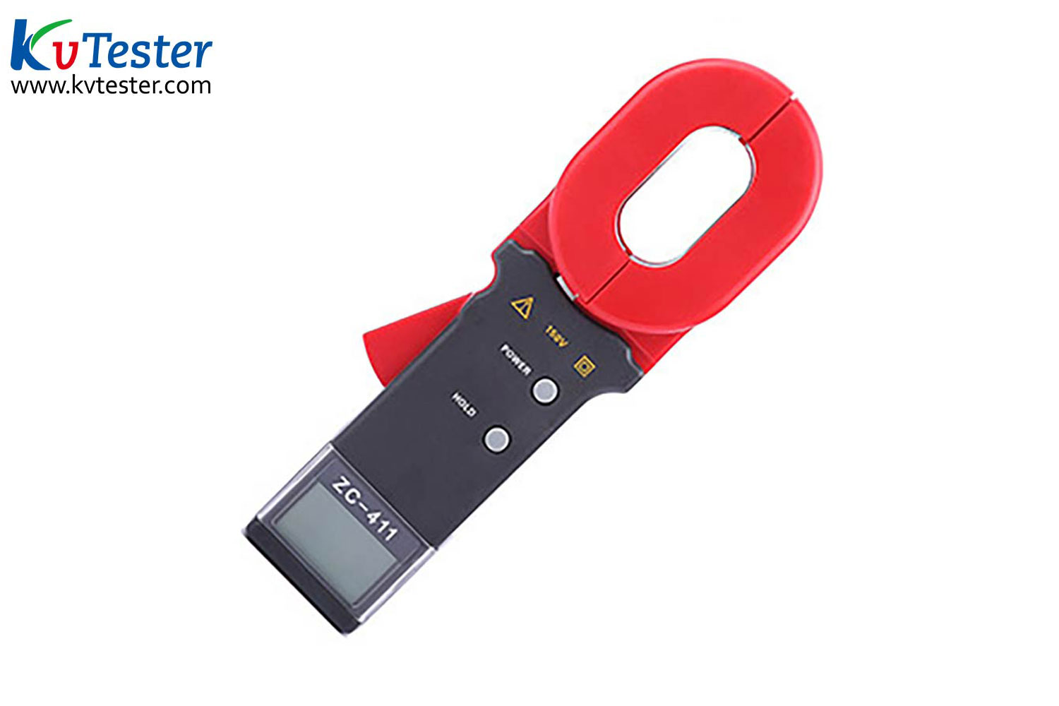
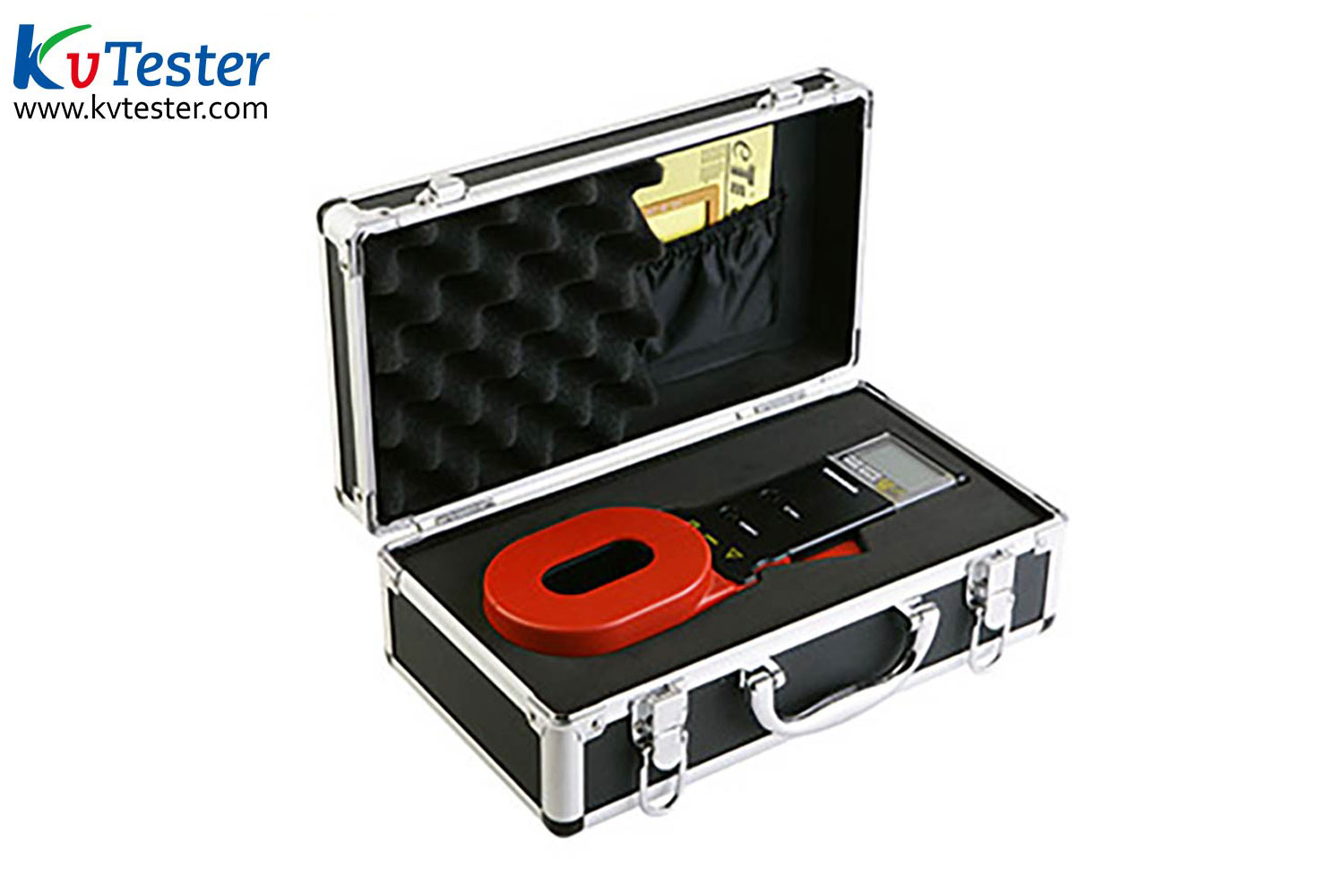
ZC-411 is suitable for measuring the grounding resistance of various telecommunications, electricity, meteorology, machine rooms, oil fields, power distribution lines, tower transmission lines, gas stations, factory grounding grids, lightning rod, etc. The current resistance of the instrument is displayed on the same screen, with a wide range and high resolution. The test results are accurate, reliable, stable in performance, and have strong anti-interference ability. It is controlled by a microprocessor and can accurately detect grounding resistance. At the same time, it has functions such as data storage and data upload.
Kvtester Electronics Technology Co.,Ltd. is a high-tech enterprise specializing in power testing, testing, research and development, production, and sales of testing equipment. It has been engaged in the electrical testing industry for many years, and its products are of high quality. We welcome customers to come and purchase.


