The three main test wiring methods for dielectric loss testers are the forward connection method, the reverse connection method, and wiring methods for special scenarios (such as CVT self-excitation method, end shielding method, etc.). The following is a detailed explanation:
1. Forward Connection Method
① Applicable Scenarios: Used when the low-voltage measurement terminal or secondary terminal of the tested equipment is insulated from ground, such as capacitive bushings, coupling capacitors, circuit breaker contacts, etc.
② Wiring Method:
Connect the dedicated high-voltage cable from the Cx terminal on the back of the instrument to the high-voltage terminal of the tested equipment.
Connect the dedicated low-voltage cable from the Zx terminal of the instrument to the low-voltage terminal of the tested equipment.
Ensure that the core wire and shielding layer of Cx are equivalently connected (but the core wire and shielding layer of Zx must not be short-circuited, otherwise sampling measurement will be impossible).
The instrument's grounding terminal must be reliably grounded.
③ Advantages: Accurate measurement results, less susceptible to external interference. Effectively reduces the influence of the surface resistance of the corona shield on the dielectric loss factor test value.
④ Precautions: The tested equipment must have sufficient insulation level; a standard capacitor may be required externally if necessary. When the test voltage is high, ensure safe operation.
2. Reverse Connection Method
① Applicable Scenarios: Used when the low-voltage measurement terminal or secondary terminal of the tested equipment cannot be insulated from ground, such as most high-voltage electrical equipment where the casing is directly grounded during operation.
② Wiring Method:
Connect the dedicated high-voltage cable from the Cx terminal on the back of the instrument to the high-voltage terminal of the tested equipment.
The low-voltage terminal of the tested equipment is grounded.
Ensure that the core wire and shielding layer of Cx are not short-circuited, otherwise sampling measurement will be impossible.
The instrument's grounding terminal must be reliably grounded.
③ Advantages:
No need to disassemble the ground wire of the tested equipment, simple operation.
Suitable for on-site maintenance measurements.
④ Disadvantages:
Measurement results may be affected by external interference, resulting in higher values.
A dedicated high-voltage shielded cable must be used to ensure safety.
⑤ Precautions:
The reverse connection method introduces a certain error, but it is usually within the acceptable range and meets the requirements of the regulations. During testing, ensure that high-voltage leads are kept away from the tested equipment or other live equipment to prevent electric shock accidents.
3. Wiring Methods in Special Scenarios
① CVT Self-Excitation Method
a. Applicable scenario: Testing of capacitive voltage transformers (CVTs).
b. Wiring method: Use a single-phase wiring method to simultaneously measure the capacitance and dielectric loss factor (tgδ) of C1 and C2. Special test leads must be used, and the instrument's grounding must be reliable.
② End Shielding Method
a. Applicable scenario: Testing of cascaded voltage transformers, especially when higher voltages need to be applied.
b. Wiring method: Open the X grounding point, connect A and X, and then connect to the instrument's HV terminal. Short-circuit all windings on the low-voltage side and connect them to the Cx terminal. Note that the X terminal lead should be kept at a distance from the terminal box to prevent corona discharge.
③ Reverse Connection Shielding Method
a. Applicable scenario: Measuring the capacitance value and dielectric loss factor of C0 at the upper end of the CVT.
b. Wiring method: Similar to the reverse connection method, but shielding measures are required to reduce external interference. The test voltage usually does not exceed 2kV.
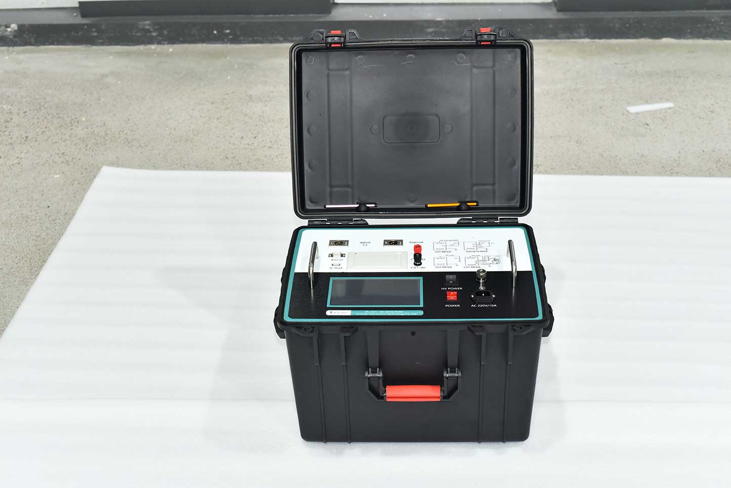
ZC-221J Tan Delta Tester breaks through the traditional bridge measurement method, Adopt frequency conversion power supply technology, use single chip microcomputer, and modern electronic technology to carry on automatic frequency conversion, analog/digital conversion and data operation. Achieved the characters of Strong anti-interference ability, fast test speed, high accuracy, automatic digitization, easy to operate.
Kvtester Electronics Technology Co.,Ltd. is a high-tech enterprise specializing in power testing, testing, research and development, production, and sales of testing equipment. It has been engaged in the electrical testing industry for many years, and its products are of high quality. We welcome customers to come and purchase. Service hotline: 0086-27-81778799, to learn more, visit the official website: www.kvtester.com


