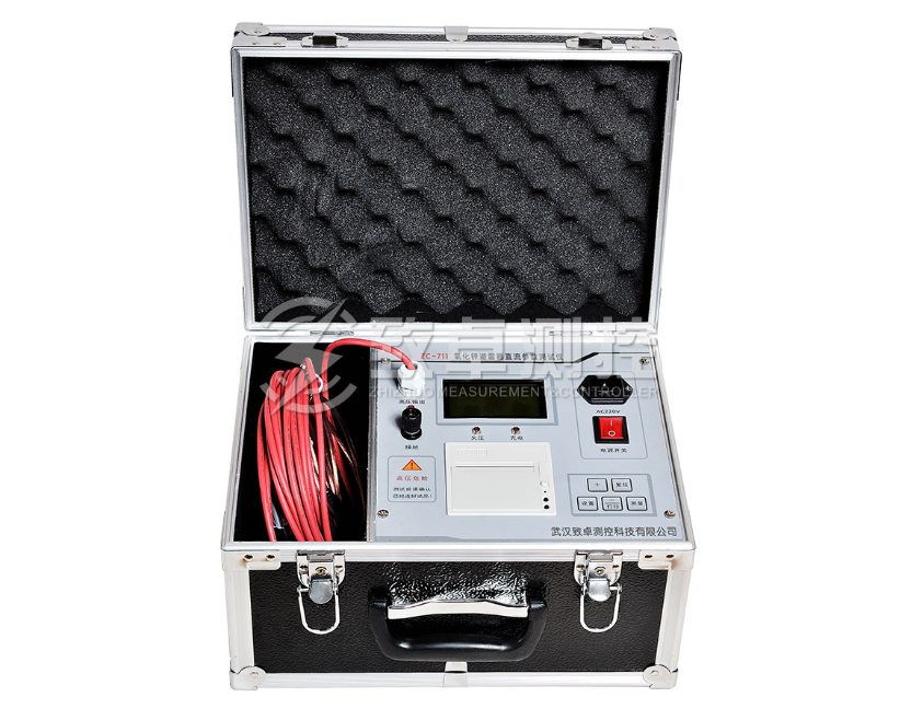
Zc-711 zinc oxide arrester DC parameter tester is a new generation of instrument improved by our company according to the field measurement requirements. It combines DC high voltage power supply, measurement and control system organically, reduces the volume and weight of the instrument. At the same time, the operation setting is more user-friendly, remote control measurement can be realized through the remote controller, and the automatic measurement of ambient temperature function is added according to the requirements of the measurement procedure, with large capacity memory, 50 groups of test data can be stored, without power loss and other features.
DC parameter tester of zinc oxide arrester
Here's how to use zc-711 zinc oxide arrester DC parameter tester:
* Please connect the test object before the test and press the "test" button!!
1. Wiring: place the arrester on the bracket with good insulation performance, then connect the high voltage output end of the tester to one end of the arrester, and the grounding end to the other end of the arrester. (as shown in Figure 2)
Figure 2
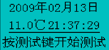
2. Measurement: turn on the power switch, the LCD module will display the welcome screen and the function prompt of the key,. (as shown in Figure 3)
Figure 3
Press the "+" key to view the previously saved data (automatically save the test results after each test)
Press the "test" key to enter the test state, and pay attention to the danger of high-voltage output!
Press the "set" key to adjust the date and time (the system date and time are wrong and need to be adjusted)
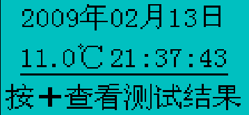
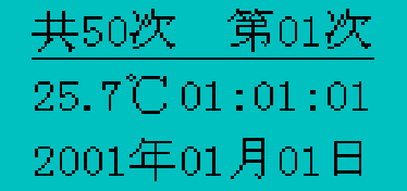
After a few seconds, when no operation automatically enters the time and date setting screen, the displayed temperature is the ambient temperature of the test. (as shown in Figure 4)
Figure 4
If you need to adjust the time and date, press the setting key to start moving the cursor in the order of "year", "month", "day", "hour", "minute" and "second". Move the cursor to the item to be set and press "+" and "–" to set it.
Press the "test" key at any time to enter the test (please confirm that the test object has been connected before the test!). (as shown in Figure 5)
Figure 5
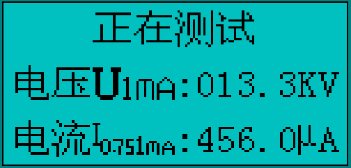
The test high voltage starting voltage rises gradually, and the current is also changing. (as shown in Figure 6)
Figure 6
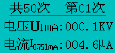
When the current is 1 mA, the instrument automatically records the voltage value at this time, and the high voltage begins to slowly drop to 0.75 times of the voltage, automatically records the current value at this time, and the test is finished. After the test results flash three times, lock the test results and save them automatically. (as shown in Figure 7)
Figure 7
3. Test result printing:
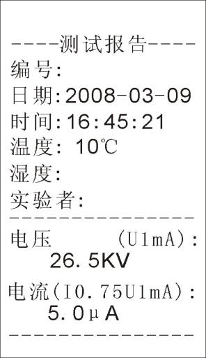
If you need to print the test data, press the "print" key, and the printer will automatically print the test results, ambient temperature, date, time, etc. (as shown in Figure 8)
Figure 8
4. Data saving and viewing:
After each test, the data will be saved automatically. A total of 50 times of test data can be saved. When the test data exceeds 50 times, the first data will be automatically overwritten, and other data will remain unchanged. The data will be stored circularly in turn.
Press the "+" key to view the saved data, and then press the "+" key to turn the page to view the last data (turn the page up circularly). The test data will cycle on the time date page and the test result page. (as shown in Figure 9)
Figure 9
Press "-" to print the currently viewed data.
5. Error reporting: if the test object is not connected properly or the short circuit is overloaded during the test, the instrument will enter the automatic protection state, stop the test and prompt the test error. (as shown in Figure 10)
Figure 10
6. Replace the printing paper: when replacing the printing paper, load the printing paper into the paper bin, pull out the printing paper, and cover the front cover plate. Thermal printing paper can only print content on a smooth thermal surface (front side).
7. Replace fuse: there is a fuse box under the power socket. Use a flat screwdriver to pull the fuse box up to replace the fuse. Fuse size is 3 a.
The above is the use method of zc-711 zinc oxide arrester DC parameter tester. If you have any questions, please consult our customer service~


