Compared to traditional grounding resistance testers, clamp type grounding resistance testers have the characteristic of non-contact measurement, making operation more convenient and safe. In many power testing projects nowadays, people are accustomed to using clamp type grounding resistance testers, but not everyone can understand their working principle. Below, the editor will introduce the principle of clamp type grounding resistance testers, hoping to be helpful to everyone.
What is the principle of a clamp type grounding resistance tester?
The principle of the clamp grounding resistance tester is based on Faraday's law of electromagnetic induction and Ohm's law. When current passes through a grounded system, a magnetic field is generated, and the resistance of the grounded system causes changes in the magnitude and direction of the current. The clamp type grounding resistance tester utilizes a built-in magnetic field sensor to measure the changes in this magnetic field and calculate the resistance of the grounding system.
Specifically, the clamp type grounding resistance tester forms a closed loop with the grounding system by fixing the measuring fixture around the tested object. Then, the tester will generate an alternating current signal on the fixture, which will cause an alternating magnetic field in the grounding system. The magnetic field sensor inside the clamp grounding resistance tester will sense the strength and direction of this magnetic field and convert it into an electrical signal.
According to Faraday's law of electromagnetic induction, when a change in magnetic field passes through a sensor, an induced electromotive force is generated on the sensor. The magnitude and direction of this induced electromotive force are directly proportional to the resistance of the grounding system. The clamp type grounding resistance tester can calculate the resistance value of the grounding system by measuring and analyzing the characteristics of the induced electromotive force. It should be noted that the measurement results of the clamp grounding resistance tester may be affected by some factors, such as external magnetic field interference, fixture position and posture, etc. Therefore, when using a clamp type grounding resistance tester, it is advisable to choose a non-interference environment as much as possible and ensure that the fixture is correctly installed and has good contact.
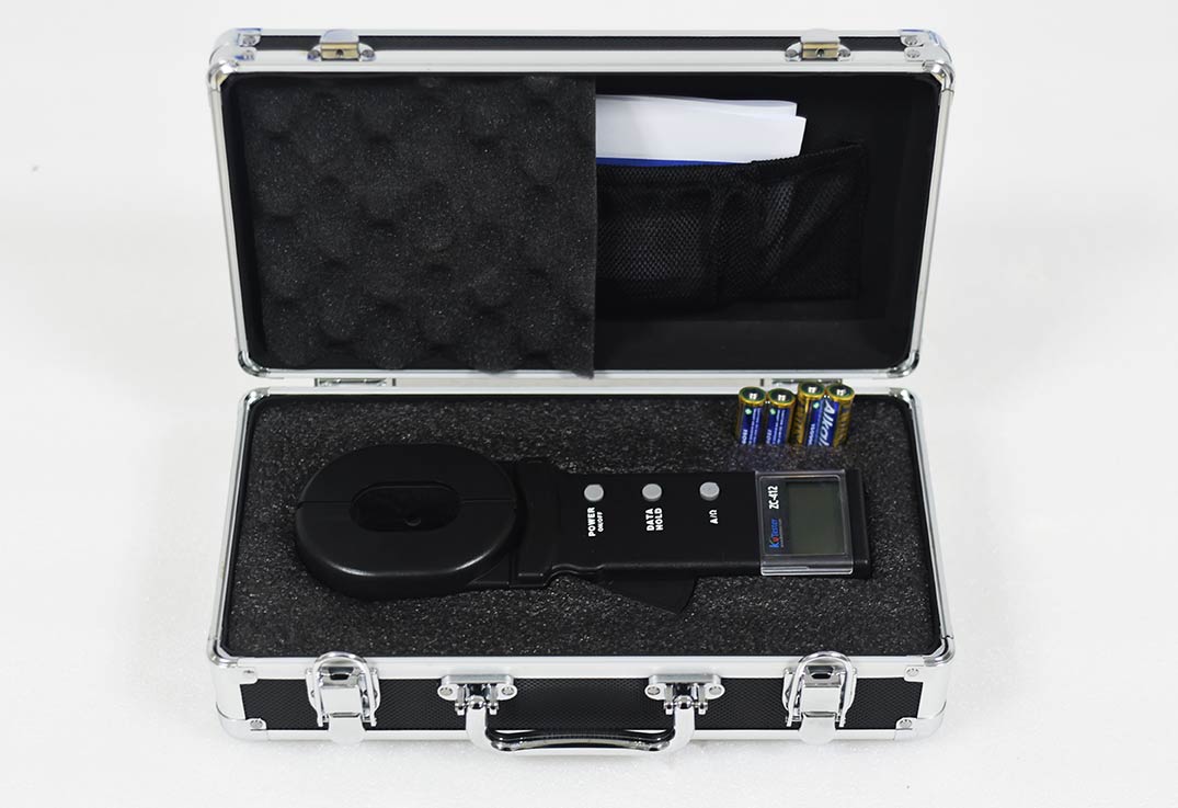
The ZC-411 clamp type grounding resistance tester is suitable for measuring the grounding resistance of various telecommunications, power, meteorological, computer rooms, oil fields, power distribution lines, tower transmission lines, gas stations, factory grounding grids, lightning rods, and other equipment. The instrument displays current and resistance on the same screen, has a wide range, high resolution, accurate and reliable test results, stable performance, strong anti-interference ability, and is controlled by a microprocessor. It can accurately detect grounding resistance, and has functions such as data storage and uploading.
Kvtester Electronics Technology Co.,Ltd. is a high-tech enterprise specializing in power testing, testing, research and development, production, and sales of testing equipment. It has been engaged in the electrical testing industry for many years, and its products are of high quality. We welcome customers to come and purchase. Service hotline: 0086-27-81778799, to learn more, visit the official website: www.kvtester.com


